I have not had much luck setting up the camera for LB. I can get the image to show up fine and go through the calibration and alignment setup pretty well too, but when everything is complete in the best case, the scale is off by 50% and nothing lines up.
I have never used a camera with LB before, but I have used all sorts of cameras with many other systems and so have at least basic familiarity. At first the issue was related to my misunderstanding the scale of the dots pattern that should be printed.
After that was corrected, I still never do end up with a reasonably calibrated image that lines up with anything in the bed.
I can complete the calibration with all images at <.3 and most are below .2 and the lens scaling and it matters not realy any at all so far… Fisheye or normal also does not seem to help. Now that I see LightBurn has their own cameras, I would get one if I thought it would help. The images at 2M are currently so poor that I would not think even 8M images would be massively clearer. Better yes, but with a larger bed like this I would think 16M would be the minimum needed. Assuming zero wasted pixel space, 1920 pixels on a bed of 810mm is only 2.37 pixels per mm, 16M is 4656 / 810 mm and that is only 5.75 pixels per mm so it just barely doubles.
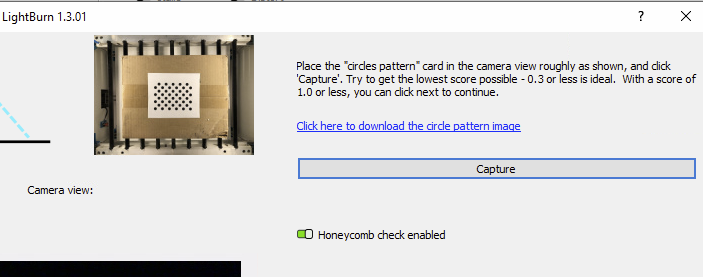
This is a little unclear. The application wizard instructions should point out that the page is NOT to be printed as an A4 or letter sized print but only 1/2 of one in portrait mode. If you download the .PNG and print it, by default Windows will print it full page and that scale is about 200% more than it should be. I think it would help if there was a note in the onscreen instructions that has the download link to tell you to print it out on 1/2 of a sheet of paper and what the dot dimensions should be.
The image has no scale shown to it but appears to the the bed of a smallish CO2 laser, while a full sized piece of paper looks about the same in the bed of my 81cmx46cm diode laser which was the source of confusion.
The online instructions do mention this, but not the wizard application screens that I ever saw.
From the GitHub docs:
“The circles image will be approximately 148mm x 105mm (5.8” x 4.1"), and should have at least 6mm (1/4") of white space around the pattern."
While the dimensions for the pattern are not in the calibration wizard itself, the dimensions are listed on the documentation and Oz calls out that it’s roughly a quarter of a letter size paper in the video included in the documentation.
The circles image will be approximately 148mm x 105mm (5.8" x 4.1"), and should have at least 6mm (1/4") of white space around the pattern.
Note that the precise size of the pattern is irrelevant, however. It’s the relative size of the pattern to the captured image that’s more important. So ideally the following would be met:
The pattern size fills roughly 1/9 the field of view at the focal distance expected between lens and work material.
You’ve focused the lens well, again for the focal distance expected
You have extremely even lighting for the pattern
You have a very blank background, ideally lightly colored. You want to maximize contrast to the test pattern. You most definitely do not want anything in the background that in any way resembles dark circles.
This is a large enough change to indicate that there’s a fundamental problem with how it’s working. Can you confirm that the focal distance from lens to material is unchanging? The alignment will literally only work properly at one focal distance.
Are you doing camera aligning to freshly burned targets that have been unmoved from burn to capture?
When you do your capture during camera alignment, can you confirm that the image is distortion free? If it’s not then that means there’s something wrong with the initial lens calibration and that needs to be corrected first.
If your lens has any distortion at all you would need to choose fisheye.
In what way are they poor? Just in terms of resolvable image? Can you confirm that you’ve focused the lens?
I suspect 8MP will be certainly better than 2MP but beyond that will be diminishing returns for a bed of your size.
What are you expectations for placement accuracy? I have an 8MP camera on a 700mm wide bed and I’ve found I can get to roughly sub millimeter placement but not better. While resolution could be better I suspect it’s flaws in the distortion correction and alignment process that limiting the accuracy before resolution limits. That could potentially flip in very large beds but uncertain.
Thank you very much for the quick response. I will answer inline…
I think you were answering while I was still editing the post. Man you are fast!
I did all of this. The lens is fixed focus and clean and looks normal in Windows using the builtin camera app and in the thumbnail window in LB. The full sheet of paper with dots is about 1/9th of the area of the laser bed but it was tried quite a few times on both full sized 8.5x11 and 1/2 size as the documentation indicated. Both plain white paper and white card stock were tried and the pages were very flat and laying on top of a single sheet of box grade tan cardboard that was long and wide enough to basically cover the entire bed to use as a blank background to eliminate any visual clutter. I used another piece about 18x18inches for the 1,2,3,4 target alignment that I could lay on top of this, and it is about 1/8" thick.
I only printed a new one of these if the distances between the camera and the bed changed for that alignment.
Mostly, but the very edges of the bed image tend to have some aspect distortion no matter what else is tried.
It has some and I have tried both ways
I would not expect it to be amazing, just clear enough to know that things are working correctly. Things like:
I can see the engraved lines from the laser (they are about .25 - .5 mm wide most of the time) and know how precisely things are being placed/engraved without go to the laser to look directly. I was going to put it inside an enclosure and wanted to be able to make multiple cuts without opening the enclosure between every cut to watch the framing run live. I can use Windows camera app to watch it move, but the actual laser tracing path is hard to see that way and you can’t really line up multiple cuts that way… I wanted enough resolution to tell when a piece that has been cut drops down a bit as it is released so I know if a another cut pass is needed on a particular cut without jostling things around first.
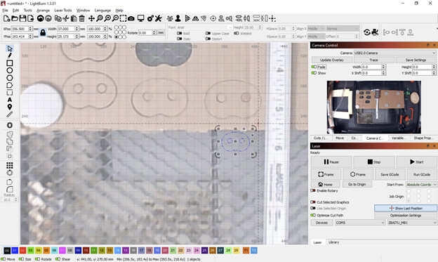
This is an example that might help illustrate.
The blue outline is the actual LB object and is about 37mm wide in LB. The cutout actually made is also 37mm wide save for the kerf so the actual laser calibration seems fine, but this was where the last calibration of the camera left things. The camera is pretty much above the center of the bed, but the image is zoomed about 200% in when I show the overlay.
When the one on the lower right was actually cut, this is the LB screen. The blue outline needed to be about 2 inches below and a little to the side for that lowest cut and the scale is pretty far off as you can see. When I framed the cut, it put the frame right where the cut really happened, it was just the image that didn’t match.
I have tried a couple of dozen calibrations over the past month or so and more more I learned, the better they got, but this scale issue I have not eliminated yet. I am fine with going through everything again, I was just trying to figure out what I was not doing correctly so I didn’t repeat the mistakes. I am sure this is supposed to work, I just haven’t found the right dance steps.
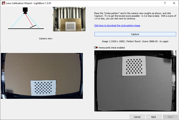
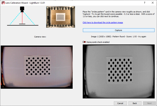
Sometimes it inverts the image between two sample images like this whether I use either of the camera interface options.
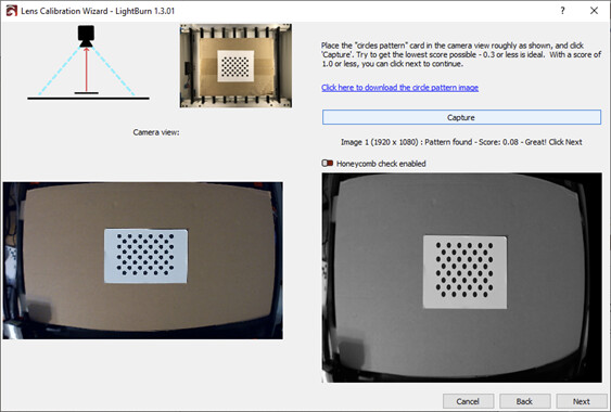
Sometimes not… You can see that things are focused and clear.
I will go and try again, though I am not really sure what to change. For example, should I use a full sized dot sheet or a 1/2 sized sheet? A full sized sheet is ~1/9th of the area per the documentation you mentioned as #1 above, but the correct 1/2 sized sheet is far less even though the documentation says it should be small. With a larger bed of 46x81cm you can’t really meet both criteria at the same time can you?
To avoid any rotation issue requirements, I have also moved the camera mount so that the native camera angle is correct. I can adjust the vertical height some, but it was not clear exactly what should be in the frame. The laser gantry and print head, the entire bed and rails, only the printable area, etc… I would have some control over how the image frames, but not perfect. It’s aspect ratio and field size versus the bed laser area and frame are fixed but the camera position can be moved. It is on a 2020 aluminum extrusion riser above the bed.
This could be a matter of exposure. I get this a lot especially if you have a light workpiece on a dark background. In that case I’d suggest using manual exposure. However, that’s only available in Custom Camera System but looks like you’re using Default Camera System based on your Camera Control window. You may be able to control the exposure in an external camera tool and have that be retained in LightBurn but not sure how reliably that works.
The live feed and the captures will always be done using the native orientation of the camera. Can you confirm whether or not you have any external tool/app potentially modifying the feed prior to it getting to LightBurn?
I’ve not heard of the orientation flipping between shots. In any case, I’d suggest not getting too caught up with the captured image and focus exclusively on the acquired score. Based on your pictures you definitely want to be using fisheye.
Note that even with an upside down or sideways capture that LightBurn will auto-orient overlays done with “Update overlay” to match your bed orientation. It uses the order of the targets to determine this. The live feed will still be native orientation.
It sounds like you’ve been switching these around. Is it possible that you’ve done the calibration process with one system and then switched to the other for use? If so, that could account for scaling difference.
If you’re able to use Custom I’d suggest sticking to it.
Concern yourself with the score. If you’re getting good scores then whatever works better in that regard is the path you want to take. I’d suggest really holding out for “Great” only scores, again making sure you’re using fisheye. Standard lens can provide false positive good scores.
Also, if you can use Custom Camera System I’d suggest sticking to that.
I’d suggest orienting the camera such that you’re taking advantage of as much of the sensor as possible. So you’d want the 81cm aligned to landscape on the camera. As for position as close to center of frame is ideal.
At a minimum you’d need a clear view of the bed. Essentially every addressable area that the laser module could potentially burn. Everything else is clutter.
When things are working correctly camera alignment is what would affect scale of the overlay. Yours seems off enough where either something is broken or the overlay is being captured at a different resolution than what the alignment was done with. This could happen when changing camera system. Custom Camera system will attempt to use the highest available resolution whereas Default will pick first available listed which may not correlate to highest resolution.
One other suggestion for camera alignment, print the targets at the largest scale possible that fits in your bed. This will temper as much as possible errors in the process.
If you continue to have issues with scale I’m tempted to suggest modifying the prefs.ini file to remove any existing camera calibration information. There was one other user who could not for some reason get the results of new calibration to be saved and was reverting to old settings. Not certain but it’s not inconceivable that something similar could be happening here.
I tried all of these suggestions but didn’t make much progress. What would be causing it to be so inconsistent? Why does a perfectly readable image in the preview windows still make for an unreadable capture from the software perspective, even though it looks just fine?
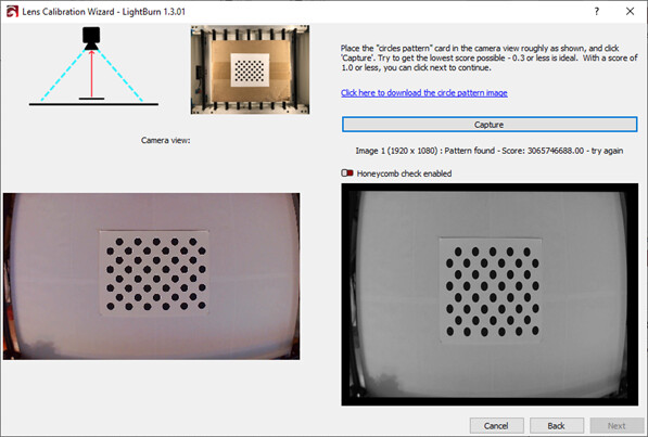
Why would a few dozen captures of the same scene cause black screens, complete warped failures, 6 digit scores and less than 0.2 scores when the scene looks the same to a human and as displayed on the LCD screen?
These many examples are a bit bizarre to me… It seems to not be deterministic…
This is a machine that really does nothing else except LB and sometimes Paint.net/Inkscape/Cura for working on models and drawings and a couple of utilities to talk to printers and network gear… Nothing that would interfere with the camera that I know of. It was a Dell laptop that turned into a 3D Printing/Laser utility PC. I wiped it and installed Windows 10 and the software it takes to run tools like this. I just went back through the applications again that are installed and don’t see anything that I think might interfere with camera access for an app like LB.
What I do not understand is why it would be so inconsistent in capturing images… For example, I just started over with LightBurn on this machine.
1/7/2023
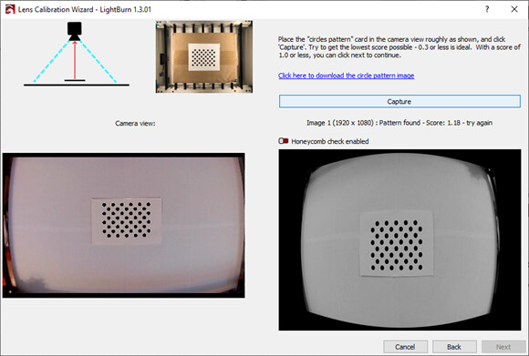
Removed Prefs.ini to start fresh, imported M81 laser and used small size pattern that matches the manual and cover a sheet of cardboard completely with white paper so there would be the maximum contrast with an all-white background. Nope, it is still not happy.
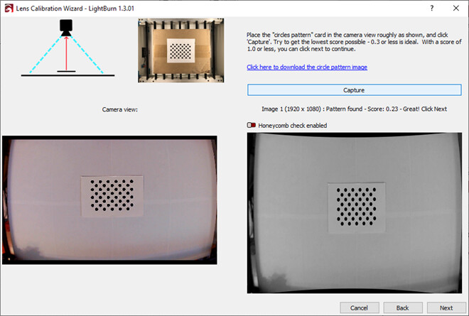
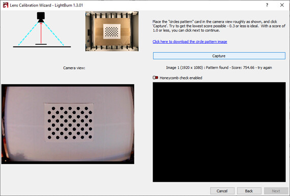
Waited about 3 minutes and changed nothing and click the Capture button again that shows this:
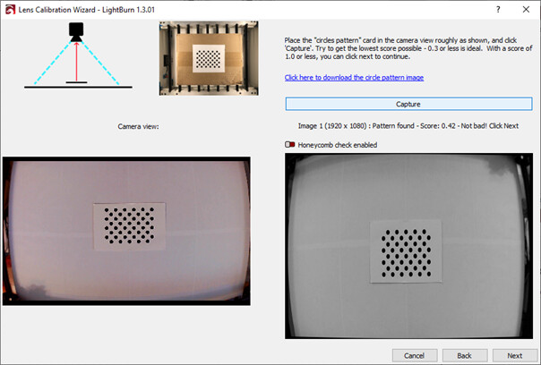
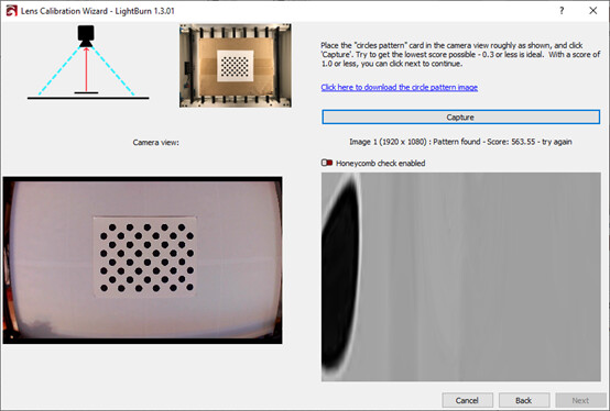
Clicking Capture a third time after a couple of more delay minutes changing nothing again and get this:
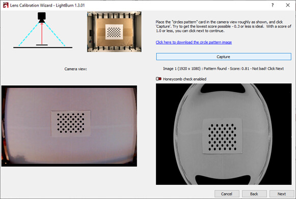
Next were .41 - .43 for about 50 or so captures with the rare 0.16 and 0.18 values or once in a while something like this:
Please note that absolutely nothing is changing…. No lighting, no camera changes, nothing other that remaining a resident of the Earth spinning around and flying through space…
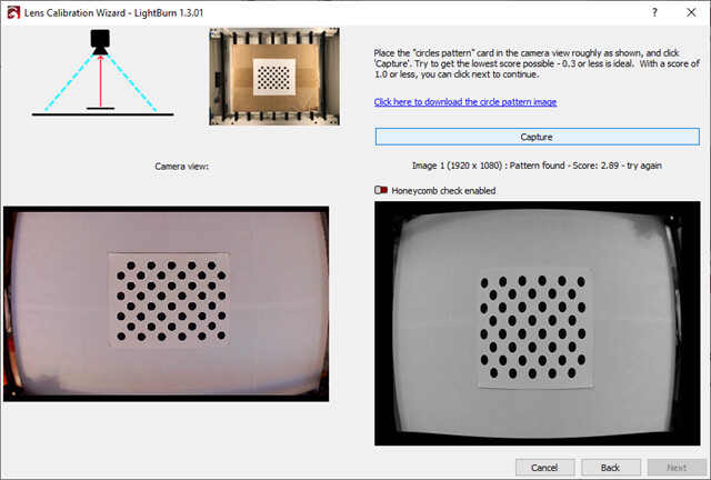
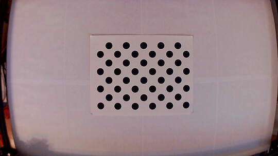
Restarting LB, turning off the Honeycomb and switching back to the full size page that is 1/9th of the area does this for the first 2 captures:
And then it shows this on the 3rd…
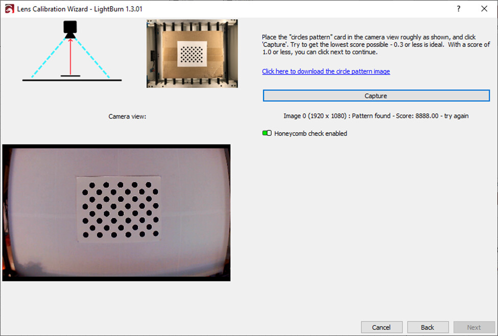
Then this on the fourth…
On the fifth:
Fresh Prefs.ini and full letter size dot page since that is 1/9th of the area
Using Custom Camera Interface
I’m not certain but I’m fairly sure this is not the case. LightBurn uses OpenCV to handle the image capture and distortion correction. In fact, I think you could actually do the entire distortion correction process outside of LightBurn and import the distortion correction values.
From what I’ve seen of OpenCV I don’t see anything in the capture or distortion correction processes that rely on RNG or anything that would make it non-deterministic.
I’ve definitely seen this. And the apparent different results with the same input. However, I think the process is just super sensitive to even the slightest variations, especially in lighting.
From what I recall from looking at OpenCV a little while back is that the score represents the average number of pixels off the corrected version of the pattern is from the original. So it’s not entirely surprising to me that there would be slight variation even with seemingly similar input.
What I can say is that I’ve had the best luck doing calibration in heavily diffused light but very well lit environments and with the camera off the machine. So basically no shadows, extreme contrast, and the ability to dynamically move the location of the pattern to optimize for score. I probably went through 10-20 captures per image to get to an acceptable score with very subtle changes sometimes leading to huge score differences.
This amount of variance doesn’t seem that high to me based on what I’ve seen of other situations. Without the consistent setup that you have I had swings of thousands in score.
So the process latched onto something it thought was the pattern but given how bad the score was it’s likely not the actual pattern. Then the image reflects part of that flawed capture. Again, don’t rely on the image to gauge how well the process is working.
If the perceived inconsistency is hanging you up I’d encourage not getting to caught up in it. It’s definitely not unique to your situation. If you can focus on getting the very best scores then that’s your best path forward.
I suspect in your you may need to further improve lighting and have the ability to manipulate the position, orientation, and distance of the pattern. Are you able to do the lens calibration off the laser? That might make it easier.
That pattern itself is definitely on the big side. Note how in the reference picture the entire sheet that the pattern is printed on is roughly 1/9 the view? You want to approximate that scale.
I didn’t think honeycomb check actually changed the way the capture was done but I guess it might.
First takeaway for me is that the capture is still 1920x1080. I wonder if there are multiple modes at the same resolution. I’ve never seen such a high score. I think that may be a new record. I don’t have much experience with using the default system so not sure if there are special nuances to it. I wouldn’t really expect that as I had thought the camera system was more about communication to the camera device but that the same capture and calibration would be applied in either case.
To be clear, I don’t think there is RNG involved either , just that the behavior of the code makes it look that way at times.
Thanks for the link. I went through some of the sample code for OpenCV methods for Checkerboard, Blob and Circle grid finders. (assuming that is what LB is using…) They take a JPG or similar image, convert it to binary and basically seem to generate a grid of corners or blob/circle centers to do the matrix camera calibration later… I am not going to pretend to remember all the linear algebra to understand all the OpenCV APIs guts, but since the finder would ultimately eat a JPG and hand back a grid, I think there is something else going on with the code and the way it is handling the JPEG images to hand off. I am not saying it is the fault of LB, but like you said, OpenCV takes care of this sort of thing in a straightforward manner. I see nothing in the OpenCV library that I could see would have such wild swings in detection from seemingly identical image captures assuming that the image we see are what is handed off to OpenCV eventually. At the very least is seems highly unlikely at least to me from the last few weeks of messing with it…
As an oversimplified example, maybe something like the image is captured using a particular grabbing API that returns an image that is not what the devs really think it is with certain types of USB cameras. Maybe it is only a partial grab, or maybe converted to B&W with certain options on some cameras before it is handed off, but if the OpenCV is expecting grayscale and so the noise in the background caused by less than perfect contrast when forcing B&W is creating too many data point blobs to find… I know this is way too simplistic to be accurate by itself, but I am just trying to illustrate a point… I do not really see how this overall observed behavior makes any logical sense. Normally I would think maybe dropping USB packets would corrupt things, or the contrast being captured was ridiculously poor, but since we can see the image so well, that is clearly not the case, and I am at a loss without looking at the code.
In conclusion, the camera ZBAITU sells/supplies is seemingly not very useful with Lightburn thus far on a larger bed. Getting it calibrated has been very unproductive with hours of trying and several dozen attempts. I also think 1920x1080 2M pixels is really not sufficient for such a large bed regardless of who provides the camera even if it would work based on all the images so far on both cameras. Maybe if the lens was amazing it would help. Without more examples it is hard to predict. Good lenses I think are key, but neither of these types have them. I didn’t know it when I bought them but I am still learning many things like this with my wallet.
Even once calibrated 8M-16M with a better lens would be a better camera resolution for this size bed I think. Especially since the 2M HD image cannot really even see a cut line except sometimes as the faintest of faint fuzzy grayish area of pixels only under special circumstances.
It has been very difficult to get the ZBAITU cameras to ever complete the calibration and even when they do it was so far off that I din;t really use it except for testing.
I do not know if it is LB or the camera, but it appears to be a little of both keeping this USB camera from ZBAITU working. Many of the comments I see calibrating other brands of cameras with LB include examples just like mine and the ones you describe where sequential captures during setup get wildly varying images/scores/results with little repeatability… No real explanation I have found thus far for the scores and why they seem to have no correlation with the image viewed especially with the way OpenCV seems to work for calibration… Software/hardware interactions should be more deterministic but these are not so far for me and at least a few others from what is presented…
I think that so far my experience indicates the API’s being used by LB have some issues with certain camera setups even though they work with Windows camera app just fine. The camera supplied by ZBAITU uses the generic windows USB camera drivers and seems to be less than functional with LB. I have two of them for laser/3D printer use and they work with Windows and Linux for everything I have tried so far except LB but they are just a cheap PCB camera like most… Nearly all of these cameras, from what I can tell are $5-$30 PCB camera modules. The extra costs include handling, testing, branding, shipping, support and the profit of commerce to keep the lights on and food on the table. If anything has a significant cost I would think it is likely using a name brand CCD like Sony and the lenses as much as anything else.
I also tried a Logitech webcam I borrowed and it works somewhat better from a glitching capture point of view but it also has it’s own driver, a somewhat better lens and does not use only the Microsoft USB Camera drivers. However, after I got it calibrated, it goes off line in LB every so often, and the 1920x1080 is still too coarse and fuzzy to be very useful. The best good scores are not better than the good scores of the other ZBAITU cameras but are more consistent, etc. While the calibration at least did eventually complete and in the center was pretty decent, it still had issues. However the Logitech lens would require ~4 feet of vertical height to cover the 81x46cm bed. At the mount maximum height of about 50cm it only covers the center 60% of the bed area. That would make the laser camera mount way too wobbly whenever the laser gantry moves and so would have to be mounted from the ceiling or something else…
I ordered a Lightburn 8M 120W camera yesterday to try and see if it can be made more predictable. According to the calculator in LB, it should be the right combination. Matching a 12M-16M module with a lens and a mount would take longer than I want to spend on the camera. I just want the laser to work for more projects, and the camera is the means to an end. One part of the STL for the case that holds the PCB needs a lot of supports and keeps failing to print in PETG. I might have to switch back to PLA since it bridges better, but PETG is more flexible and seems to work better for me when used for parts that move and need some flex. Normally I would print it on the side, but there is a round bump in the sides for the lens that prevents it from working better in that orientation. I only have a single filament printer, so dissolvable supports are not an option. Our library has one with dual extruders so I might give that a try if this fails much more.
I have tried both Default and Custom with similar results. The Logitech is better, but not by much. It is still not able to functionally see thin engraved or most cut lines. Filled areas only show up if they are 1mm or so or more…
Lighting was pretty good I would think, so I think the cameras are likely to blame again. Within about 8 feet of 5x100W equivalent LED/CFL lighting at night (not dimmable so PWM lines are avoided) and also near enough to benefit from a WSW facing window during the day and both times have had similar results
I haven’t pull out a real light meter yet but my phone version at night shows 258 Lux at the camera face. I tried adding more LED lighting temporarily, but the LED source I chose seems to use PWM for current limiting even on 100% so the stripes of frame rate vs PWM start to appear. I will see about getting a better light source setup this week.
Adjusting manual brightness in LB might help as well. I will play around some more… I think it will be a while before the new camera shows up so hopefully by next weekend I can try again with it. I might even build a desktop PC to start everything fresh and eliminate any potential USB issues or other unknown conflicts, they just take up so much laser work area space when compared to a laptop.
Thank you again and I appreciate all of your help and suggestions and have learned a good bit. Eventually this will work, I just didn’t expect making the camera and laser line up would be so time consuming of a task.
This is definitely a rabbit hole type of thing. But the time invested can pay off in quality of life down the road.
I do hope the LightBurn camera works better. I worry that you’ll run into some of the same issues. Note that the 8MB 120 is known to be difficult to calibrate. The good news is that you could fall back to the pre-calibration if that proved to be a problem. No doubt it will be easier overall than what you’ve been seeing.
While I’ve been able to slowly coax out reasonable scores in various lighting situations it went to easy mode when I had ideal lighting. Bright overcast day with a ton of dispersed light, no shadows, camera off bed, flat pattern, nothing in background. Just me holding up the card by hand in front of the camera.
They link to a code for a command-line application that can also do this calibration. If this works better you could transfer the correction matrices into LightBurn .lbcm file and import.
I assumed the wide angle ones are more difficult given what I have been learning so thanks for the heads up. Since I have a wide angle laser bed, it seemed to fit better, but at a cost in time I am sure. I got the wider version bed for just a couple of specific jobs, (some family portrait engravings I am planning for this year) but everything else has been complicated by that decision. This is a moderately low cost higher power (20 optical watts claimed) laser with a slightly undersized 2020 frame that really needs to be bolted down to remain solid. I managed to cut some black recycled 5/8" UHMW PE sheet yesterday though the edges are a bit melted and it took about 12 passes at full power.
The camera mount over the frame is a weak spot as is everything else about it except the laser head itself. I got what I paid for, so it meets my needs, but just barely. I’ve been doing some glass engraving and acrylic cutting and a CO2 didn’t fit the budget what with water coolers, vents, short lived tubes, iffy power supplies, non GRBL controller upgrades and spotty quality in many of the import units. It was hard to keep it overall below $1.2-1.5k US when all was done with CO2, new or used. The lower powered diode options often struggled with glass, granite and stainless marking/engraving which was something that was most interesting to me at least… Someday I might just change the frame rails to the smaller size and move on with a smaller size for the bed once these larger projects are completed over the next year or two…
This looks interesting. It would be interesting to calibrate several of the and a couple of other cameras in a known setup to see how they are really setup.
I have access to a large plotter and can do a single sheet of a checkerboard or dots that is say 3’x5’ and that would make the calibration job massively faster. It would be awesome if that were an option built into LB! Just one calibration capture and you are done instead of 9 and many failures!
With the example code, I might give those options a try.
Awesome. That’s a level of pre-planning I find admirable. Or perhaps you just used that as an excuse to get yourself a laser. I find that admirable too.
You’ve definitely hit many of the “hidden” costs. There’s certainly something nice about a solid state solution like a diode laser. Compact and always ready to go.
One thing that you should familiarize yourself if you’re not already is LightBurn’s Print and Cut feature. It allows you to effectively burn larger pieces by breaking up jobs into smaller sections and relocating the material relative to the laser for each section. In some scenarios this could give you a larger virtual addressable area than otherwise available to you with a smaller frame.
I recall reading that Oz initially experimented with some of the other patterns and settled on the offset circle one for a reason. But I’m sure the others may be better under certain circumstances.
Please let us know how this fares. Could be useful to others. Note that it’s entirely possible that there’s already another more robust tool available that could do the same thing. I didn’t look particularly hard.
Those are both good! I assumed that I am going have a pretty steep learning curve to work out the many material options with the laser. Kind of like the 3D printing I am trying at the same time. Lasers are easier I think since the printer filament chemistry and physical slicing/extrusion/movement parameters are so varied and 2D is more obvious than 3D while also being faster to try things a out…
Lasers are some what material specific, but with only one or two laser types to worry about, it is not too bad.
I found a commercial tool that looks good but with a very short trial to test and a few hundred to use. I might try it as a comparison during the trial when I get some time to try to cobble together some of the Python code to see if I can get something to work.
Here is the commercial product… Overkill to be sure, but way cool… Would be awesome if it was part of LB, but their licensing seems way to steep and LB is not machine vision… Still cool though… Might be useful to compare it’s results with those in LB though as well…
I did a little more digging and note that the core openCV releases have precompiled binaries. One is called opencv_interactive-calibration.exe and looks to be able to do the lens calibration. Might be worth looking at.
The LB camera came in and does work better. It is not actually mounted well just yet, but my temp mounting showed it was a distinct improvement.
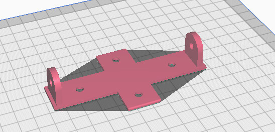
The mounting bracket STL you can download for it was a bit difficult to print in PETG (for some part latch flexibility when snapping the pieces together). All the parts printed well except for the base where the PCB for the camera goes. I did not find a good way to get it to print cleanly. The way it is designed, you need a lot of supports where the PCB goes unless you can bridge the width of the frame (a bit less than an inch) and still maintain a smooth surface upside down as a 100% overhang. I didn’t have much luck with that. I switched to a PLA blend that handled that feature better and it helped a bit, but it is still not a smooth finish inside that cavity that prints inverted. Strange design to print unless you have a dual filament extruder with dissolve-able supports or an amazing part cooling system that lets you print in empty air an inch from any walls…
Also the bracket you mount it with is designed without any mounting holes and is supposed to be used with double stick tape. I do not find that usually works upside down like that for a long time and it makes adjustments hard. In any case it also faces the wrong way for diode laser open frame camera mounts. Those typically use a 2020 open frame rail from one of the long sides and the long side of the wide angle camera
I make a new base for it that has 5mm bolt holes for the frame V-groove slots and lets you mount it rotated 90 degrees so the long axis of the camera lines up with the long axis of the laser bed instead of 90 degrees off.
It took waay too long since I don’t create 3D things much and so I first had to learn FreeCAD which seemed easier than Fusion 360 for a single project.
The mount is rigid now and should not move around and is also facing the right direction so hopefully I will get some time soon to try aligning things up better. The included profile for the 8M-120W is better than the ones I could set up before with the other cameras, but only a little and still are not very accurate even in the center of the bed.
Curious how did the 8M 120W camera work for you with your registration issue you were having. We just bought a Boss LS2440 CO2 laser and purchased a 5M 66W camera from LB and are having the same issue with registration. we can calibrate just fine but once we capture then want to line up an image we are off. The tech from Boss says that going to a 8M camera would help. Just curious if it helped you out with your registration issues before I pull the trigger.
Given the size of your bed your current camera gives you something around 3-5 pixels (assuming no waste) to resolve that much difference. Going to 8MP would get you around 5-7 for the same amount. I could see it potentially helping slightly but you’re already pretty close to practical limits although you should be able to get at least a bit better.
Can you confirm if you’ve tried adjusting the alignment with the controls in the Camera window? I’d suggest adjusting scale first, then position using markers placed as far apart as reasonable.
Yes we have adjusted scale. But we have not tried moving our targets (markers) out as far as possible. We do have a 8MP 75 degree camera on order will see if that helps.