Hey!
Hoping to get help! have read and read on the forum but have not found the exact help or did
not really understand it maybe.
Attach pictures that hopefully can explain what I do not understand.
New Master2 / 2S max 460x810 mm.
Have I bought and instead of testing it… I disassembled it and mounted it on my self-built frame.
This is a test frame and the idea is that it will be 1500x1500 mm.
Facts:
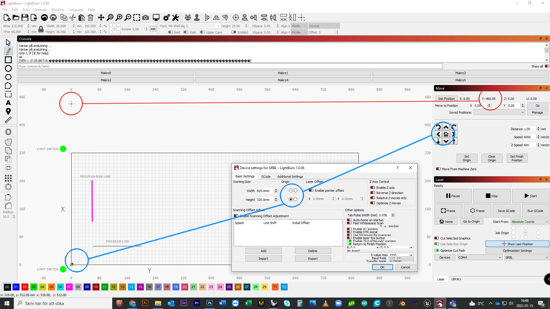
Existing cutting surface , Y/W 820 mm X/H 320 mm
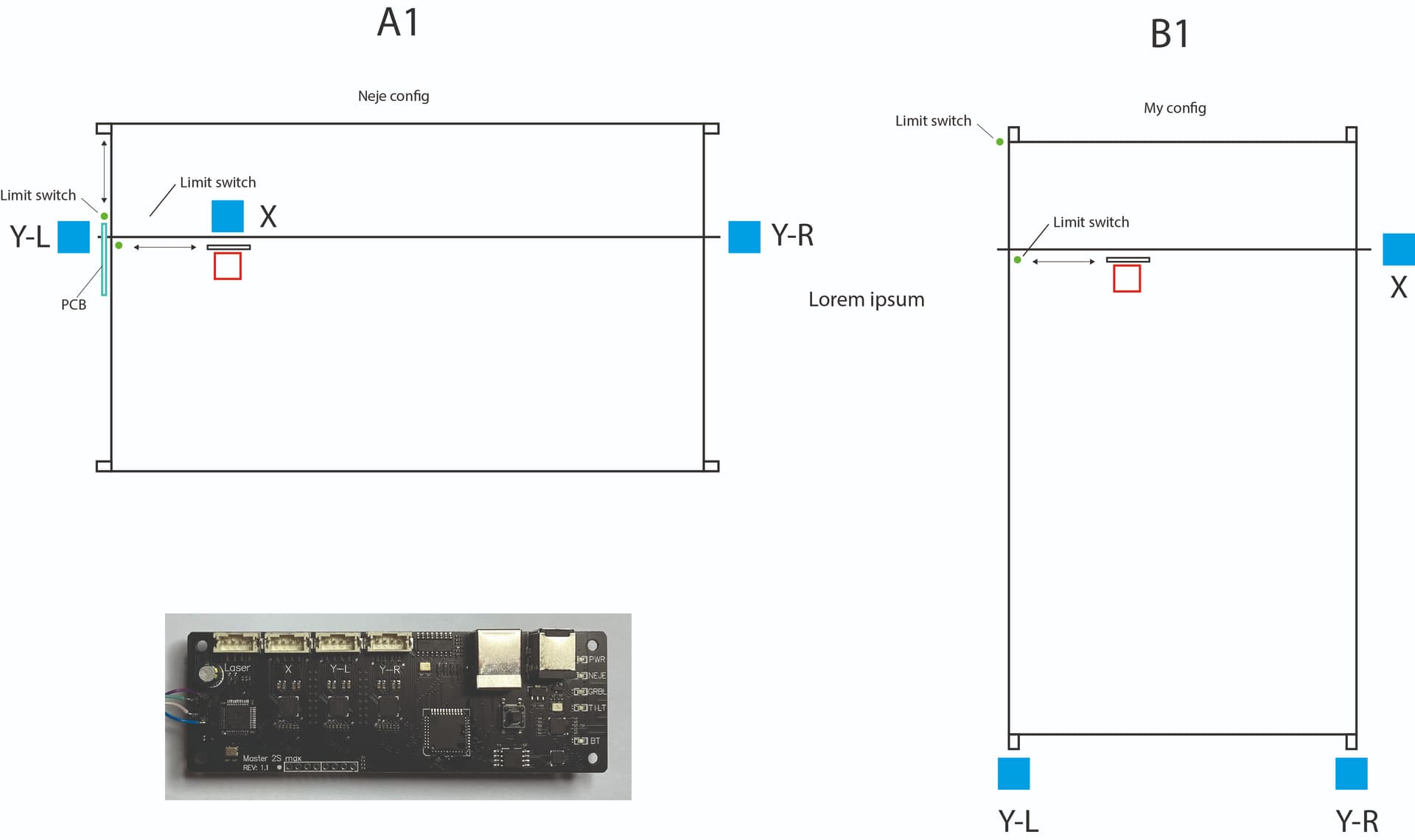
When I press the arrows for direction, they work in the directions I want. (Blue In picture)
Has 2 limit switches for home search. (Green In picture)
The home search works fine, it goes to the lower left corner as shown in the picture.
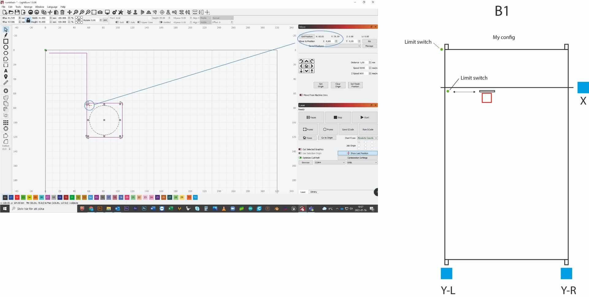
When this is done, home are on “move” (Reed In picture) X: 0 Y: 0 Z: 0, but if you press “get Position” Y changes to 460 and the small cursor appears in the window as in the picture.
I have also added a “line” (Black In picture) to test a run, but when it is run it is on the wrong axis in relation to the image. (Magenta In picture)
So somewhere it has gone wrong in the direction and I have read about similar problems, I am not so technical and have probably thought and done wrong in some connection.
Please help me so I can move on!
Thanks in advance, Petter greets
I’m going to have to hunt around. You should search the site for the origin issue. I think with grbl you can tell it to flip coordinates or something. I’ve seen it a few times on threads here.
It looks like it’s set up about as best as I can tell.
Hang in there, someone will pop in soon with a better answer.
Thank for you the well composed problem statement.
A few questions to better understand your situation:
Have you made and GRBL configuration changes after building the extended frame? If so, can you call out what those were?
Have you changed the location of the limit switches relative to the original frame?
You have oriented the machine “sideways” with the width wider than the length. Was this a conscious decision?
A few comments.
Neje machines typically will home to the upper-left. You have moved this to the lower-left. Is this a preference? Most convenient? What’s the reasoning? Trying to understand if this is important to you or if you’re fine customizing away from Neje norms.
Neje machines while homing to the upper-left will set the origin at the lower-left as you have it. Again, is this a preference or something else?
Can you run these commands in Console after doing a homing operation and return results here please:
“Have you made and GRBL configuration changes after building the extended frame?”
1: I have done nothing but plug it in and start. So the answer is probably no.
“Have you changed the location of the limit switches relative to the original frame?”
2: When you say that, I discover that I probably have it, so both yes and no and it has to do with question 3.
“You have oriented the machine “sideways” with the width wider than the length.”
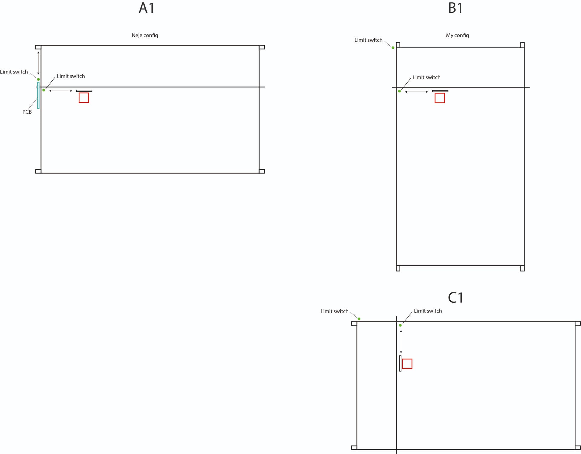
3: I may have changed direction and I have not thought about it, it is true that Neje has his homing in the upper left, but I thought that was what I did just that I have turned my machine, see attached picture. A1 is Neje and B1 is mine, think they are the same but maybe it should be like C1 !?
Conclusion: It does not matter where homing is as long as it works I will try to change the limit swits tomorrow and try again!
If you go with the landscape orientation you may want to consider swapping the wiring to the steppers so that the long horizontal axis is X and the short vertical axis is Y. Otherwise you’ll always need to do the shift in your head.
If you do that and change the limit switch locations (and the wiring for those as well) then current GRBL configuration for homing and origin should work. Lower left should be 0,0 and homing will go to upper left. You may need to invert the motor direction depending on how the belts are setup with the motors.
One set of GRBL configurations you will for sure need to make will be for working dimensions.
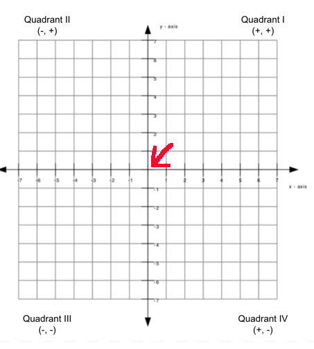
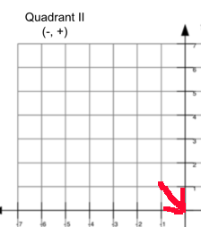
If your machine homes in the front/right your ‘work area’ is in Quadrant II
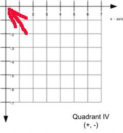
Home is rear/left the ‘work area’ is in Quadrant IV
These machines are addressed (absolute) with only positive values as most are ‘unsigned’ type storage locations.
If in Quadrant II (or III), an increase in X will move the head to the left. In Quadrant IV (or I), an increase in X will move the head to the right.
Quadrant I (or II) increase in Y head moves towards the rear. Quadrants III (or IV) an increase in Y moves the head to the front…
Just moving the ‘home’ location in itself doesn’t usually ‘work out’ right. There are usually other items that need to be handled in the firmware/configuration.
Make sense?
Did you want to work in ‘portrait’ mode? Longer Y axis than the X axis…
Hi again, ok, My final plan for this machine is a workbench that extends a minimum of 1220 mm x 2440 mm which is the standard size of board material in Europe I think.
But my little test machine that we talked about now I can fit in my study.
As it looks now I can not change X and Y because the circuit board does not allow it (see picture) it has 2 x Y and 1 x X.
Have I really changed the machine’s config? Except that I changed the length of the X and Y stays.
($ 130 = [X dimension - 820?])
($ 131 = [Y dimension - 320?])
What exactly does its command do, other than what I set in the Light Burn console
Thank you so much for trying to explain to a novice like me
Hi and thanks for your reply
I think I expressed myself a little carelessly in my comment and will try to explain myself more clearly.
What I meant is that for me in my project with my machine, it does not matter to me where the starting point for homing lands, I can turn the table surface in any direction that suits but I want Light Burns representation of the work surface to match the experience of the machine the table then me and my smarter half (my wife) will get into the charts because it was a bit over my head
And as I described in previous posts, it is desirable to have a shorter X and long Y to get as much stability in the machine as I want X = 1200-1500 mm
Ok. After your comments, I have now come a long way!
Actually do not really know what I did but it works, half way: 9
I now get the machine to move as it should (see picture) set up a test frame and ran (Magenta) but
The Y axis has stopped homing so it stops after the “frame” job, and then the cursor position changes, (Blue) and controls where the machine should start next time, which means that the machine works / eats in the Y axis.
If I do not manually pull back Y to the upper left .
X works so I can go home in the X axis.
Is there anything I can do to get Y homing working again ??
In this case then I think you’ll need to keep it. I think it might be possible to hack a custom firmware to swap how it treats those but outside the scope of this conversation.
In this case I think it will be easier to conceive of the laser in the orientation that you’ve shown it in B1. As in you’ve extended the bottom farther.
Assuming that then it’s really just a matter of getting the configuration of the dimensions in LightBurn and GRBL correct.
the $130 and $131 changes the internal GRBL configuration in the controller. It’s the controllers understanding of the laser’s dimensions. This is independent of LightBurn’s configuration for workspace size. Although these are independently configured you’d almost always want these to match.
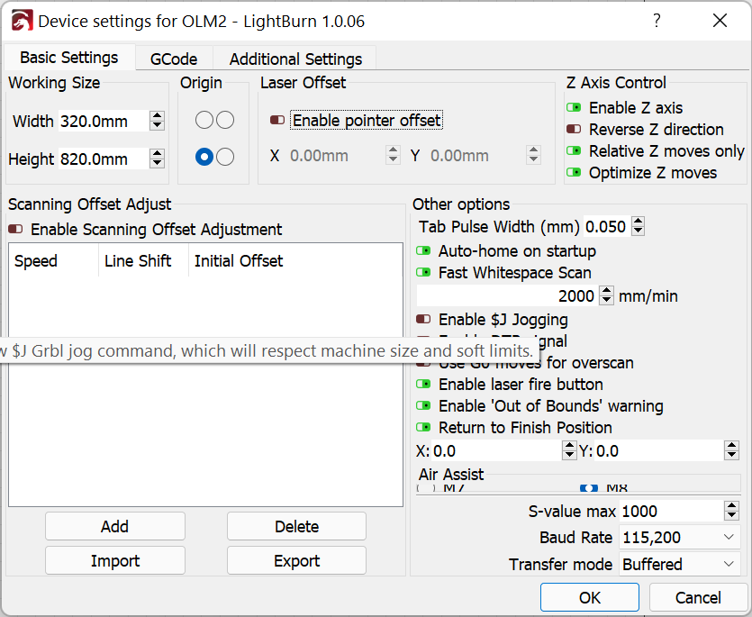
So in your case for LightBurn you’d want to set it up like this. So it’s skinny and tall and the origin to the lower left:
Then you’ll want to set GRBL configuration to match:
$130=320
$131=820
Before doing this, take a backup of your configuration in Edit->Machine Settings. Typing $$ in Console will also get you a full list of all configurations.
Once done, your position after homing should be 0,820.
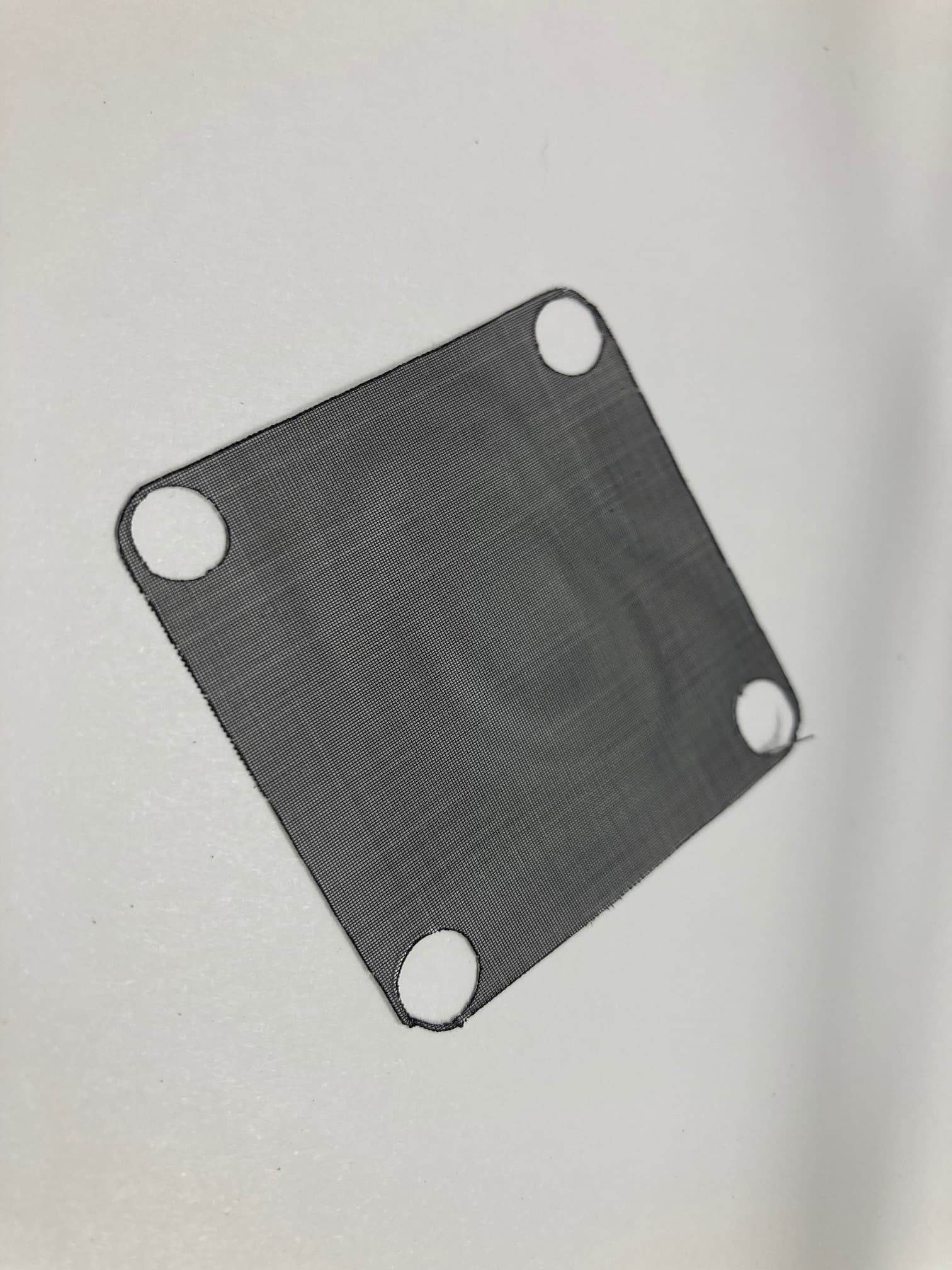
Sorry Jack, but I bought a net bag from a store in Stockholm called Granit. But they do not seem to have them left. it’s a super fine net in poyester I think, almost like stockings

 I will try to change the limit swits tomorrow and try again!