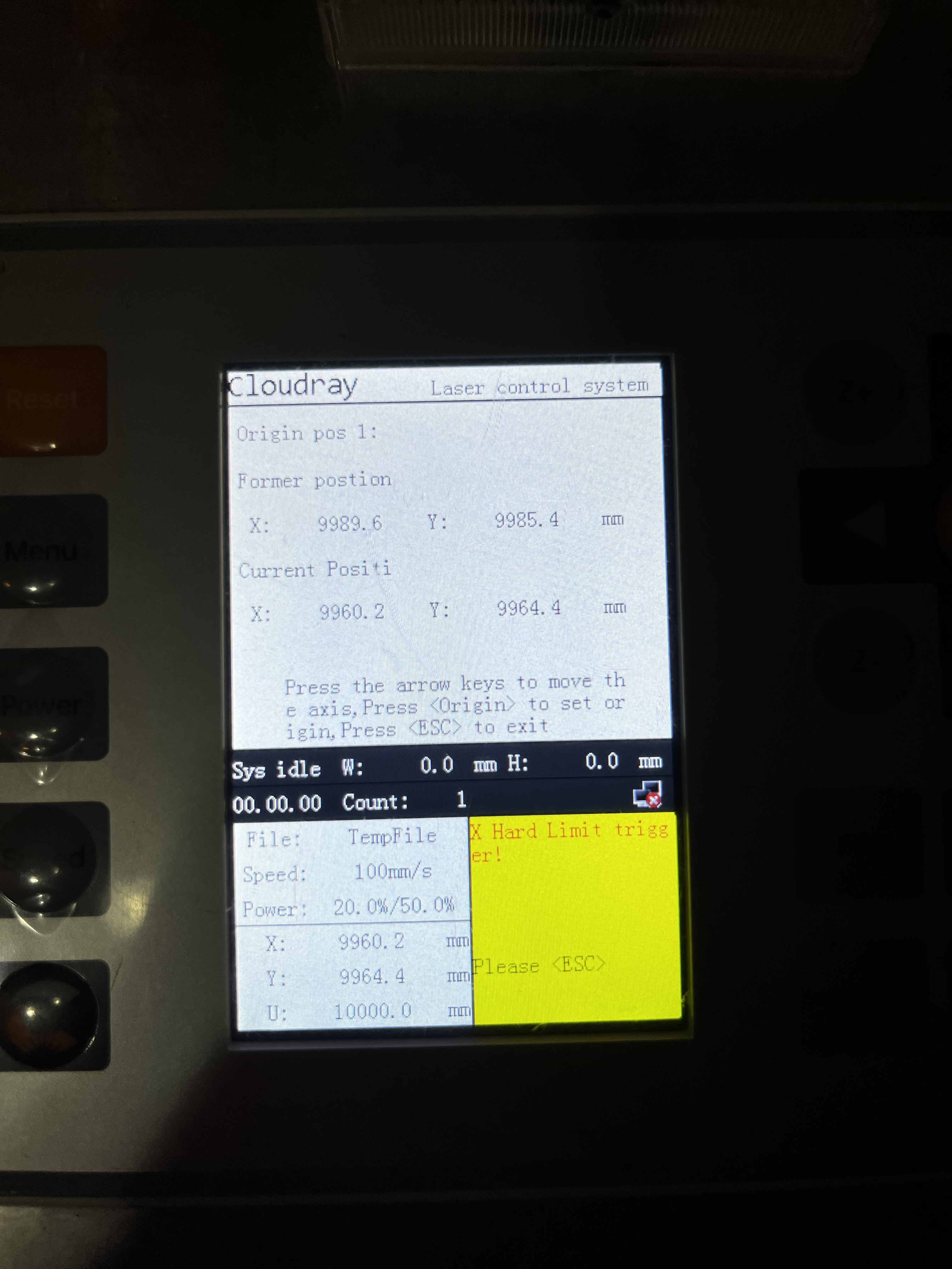
This is my first experience with lightburn. I have a ruida controller rdc6432 with a bed size of x900 and y600. I’m using proximity sensors for homing. I can’t figure out why it’s not homing properly. The machine moves to the right location but it slams the sensor and keeps grinding. On the controller it gives the hard strike error. I have attached photos of my settings. Hopefully someone can tell me where I’m going wrong. I can’t get it to locate 0, 0. On the controller it keeps thinking the x and y are in the 9000mm range.
Is this a diy?
A Ruida has limit and home switches… do you have both or just home switches?
If it’s a diy, how are they wired to the Ruida?
![]()
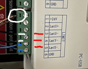
Although the Ruida placards the connection as all being limits, they are not handled that way internally. The - labels are used to home, after that it completed that operation, they are not used again. The limit switches connect to the + inputs.
In order to have home and limit switches, you need 6 switches on a 2d machine or 8 on something with another axes.
When it slams the end, does the switch indicate active?
Are these illuminating sensors, so you can tell when they are being triggered?
I notice two black wires and a blue to home, a blue wire is grounded.?
What color does what on your inductive switches…? Do they complete to ground, are they open collector? A link to the switches is always beneficial when trying to get a machine up without having it next to you.
What does the Ruida leds show when it boots?
Short video, may help…
![]()
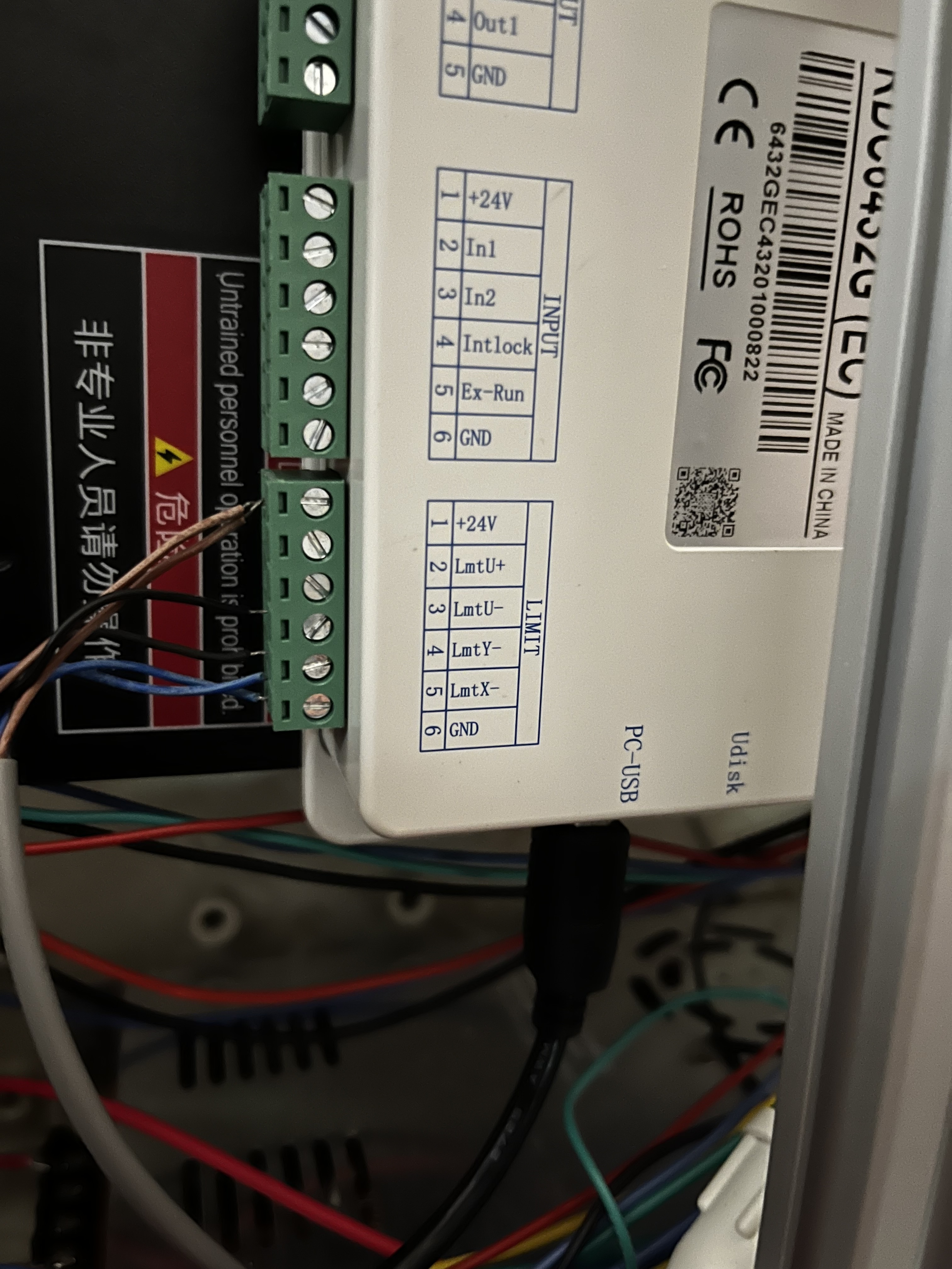
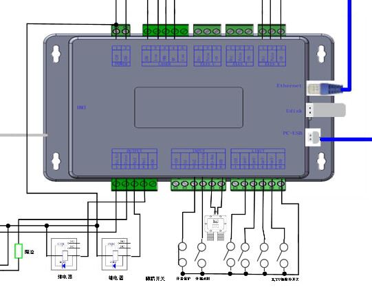
Looks to me like this controller is limited to 4 switches total.
It has inputs for X, Y and U… no Z input… Red points to the three inputs. It’s also a 6432 controller… There is also only a single real limit switch…
If the limits are open collector, you wire them together at the input… it’s just an open collector hardware wired OR.
Curios that both the bottom wires are blue (blue marks)… but one is grounded… different 24V feed wires in the white circle?.. I requested a link to his switch…
This is from my 6432G manual… shows only four inputs for limit switches.
He doesn’t use or have limit switches, he should probably turn the limit trigger option off in the configuration.
![]()
Perhaps these inputs are pulling double duty for U and Z.
Here is the wiring diagram for my sensor.
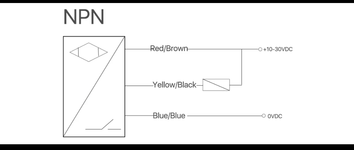
It looks confusing on the picture but the browns are connected to 24v and the blues are connected to ground. The black goes to its respective axis x and y. I use u axis as my z axis and it works fine. The sensor will function properly when a metal object comes close. Here is my other concern is the coordinates that the machine and controller are reading.


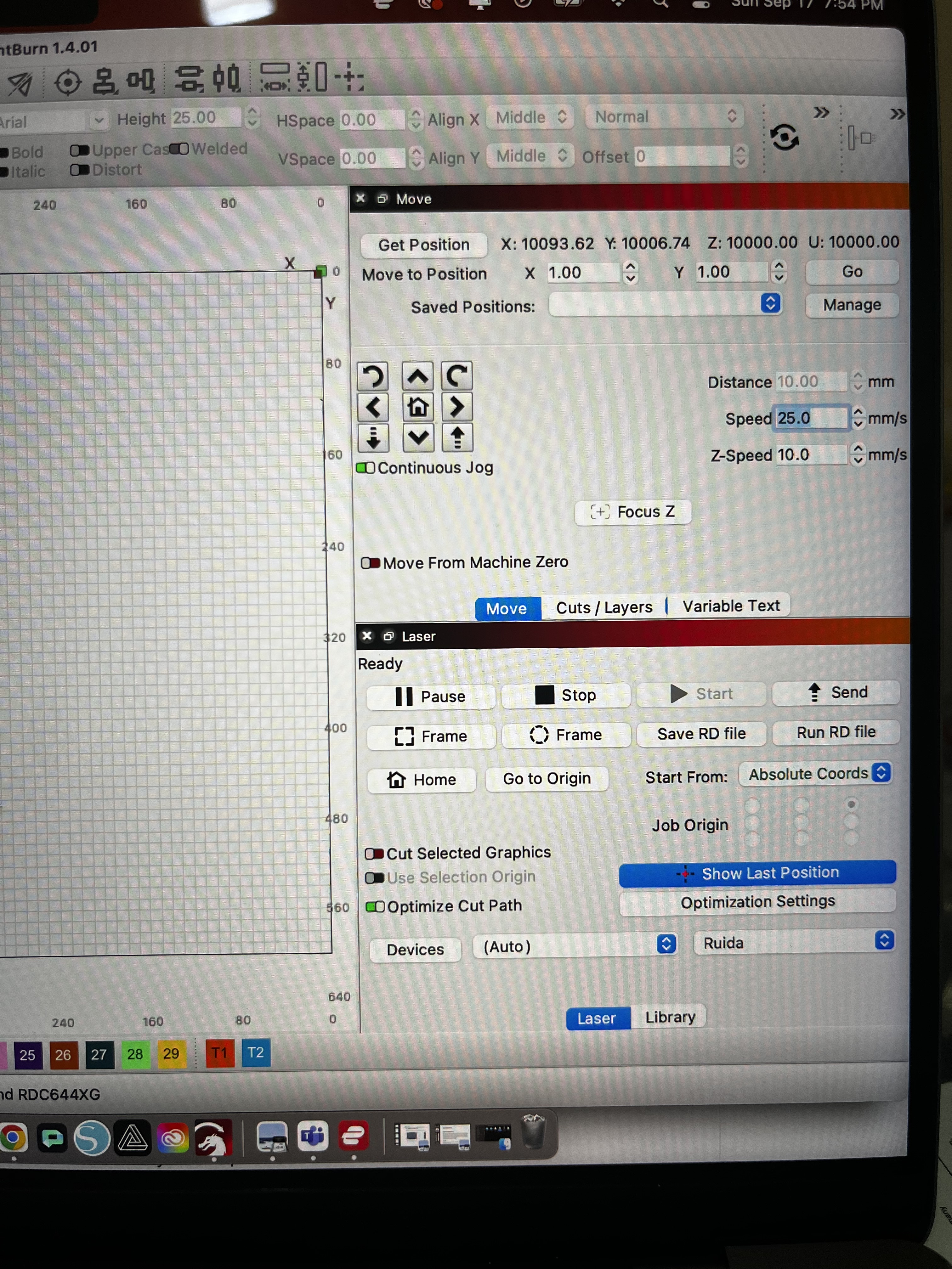
I can’t figure out how to get them to 0 in the correct position. Also the steppers act different when I got through lightburn and the control panel.
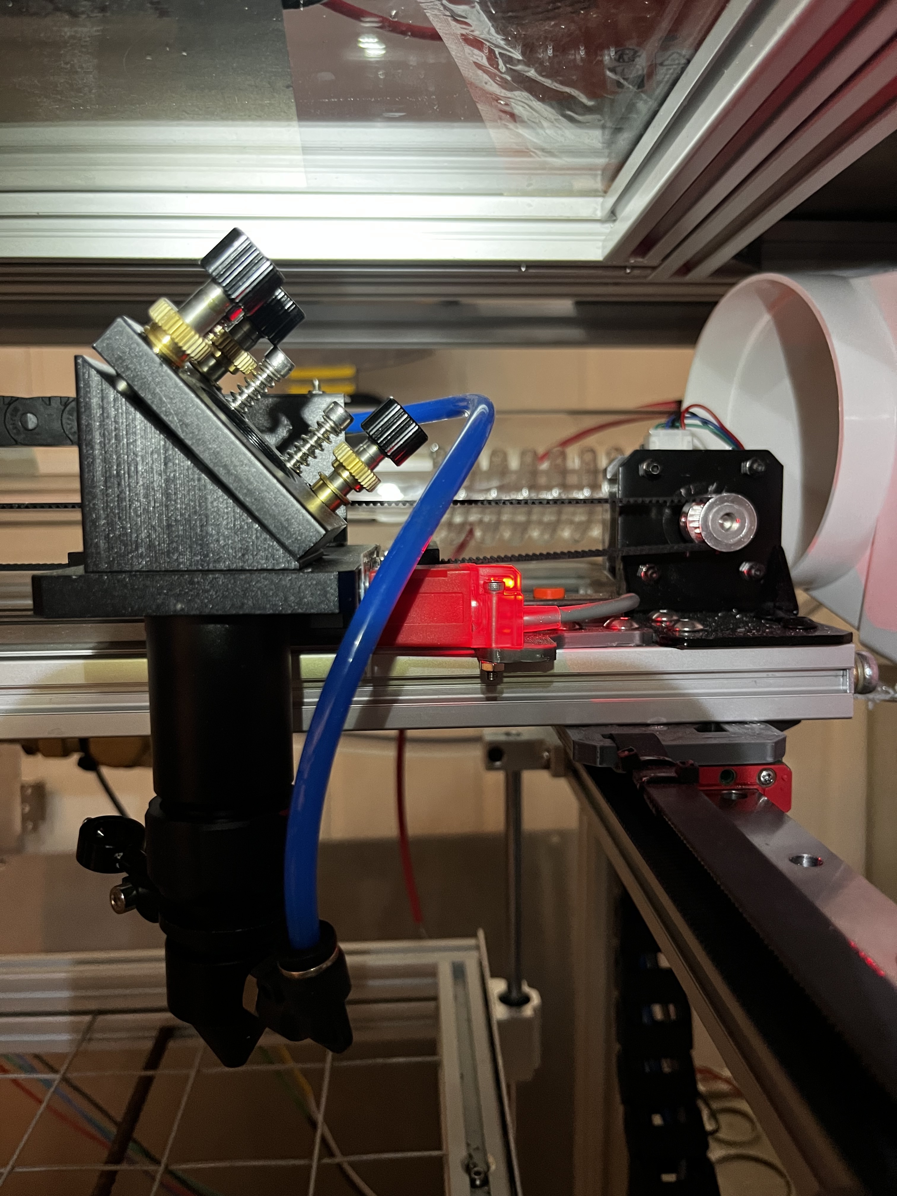
Ah, but do they light up when the machine approaches as part of the homing cycle? ![]()
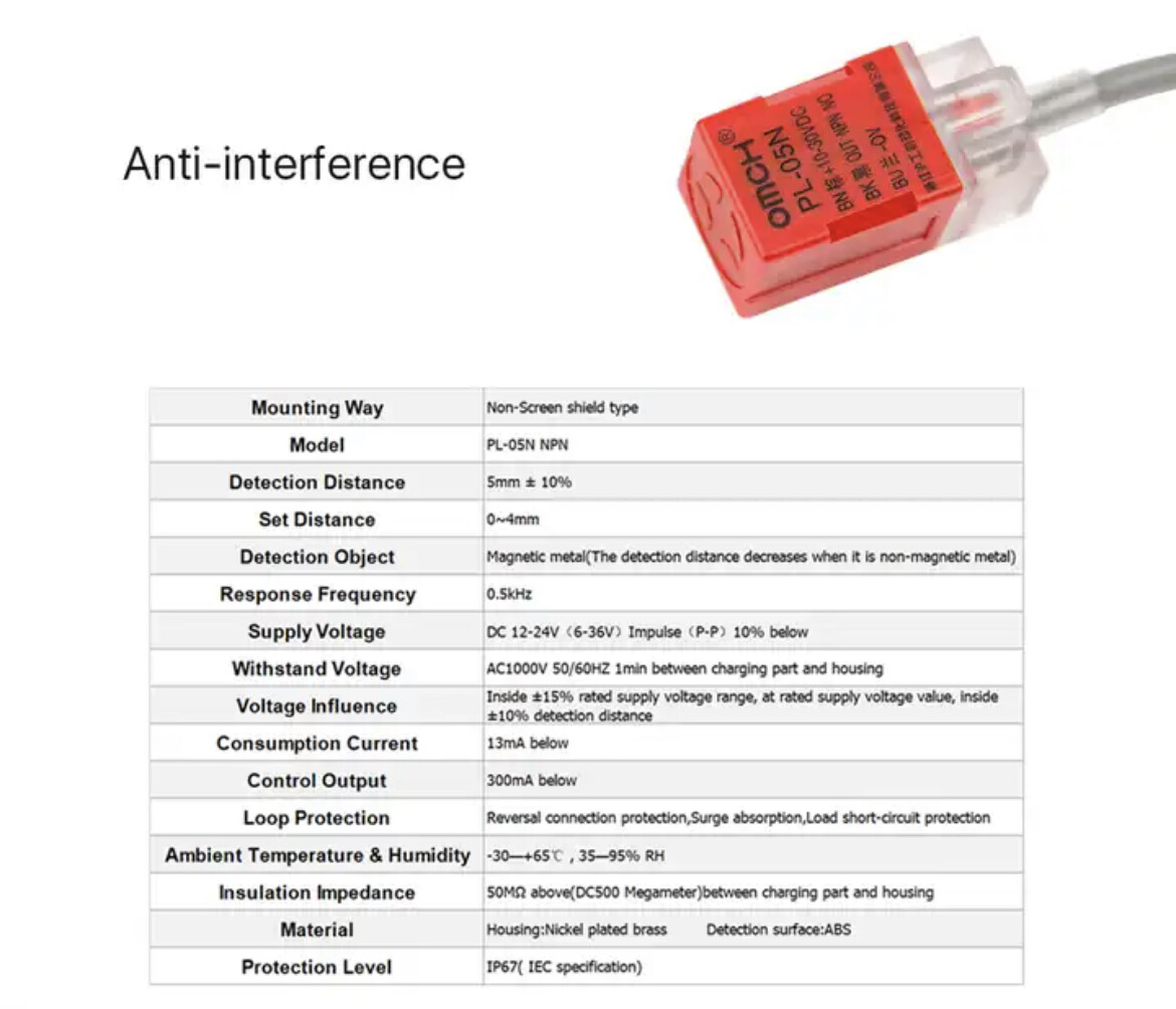
The target mark on the end is the sensitive area and works best with steel, although aluminum & brass will trip it at closer ranges.
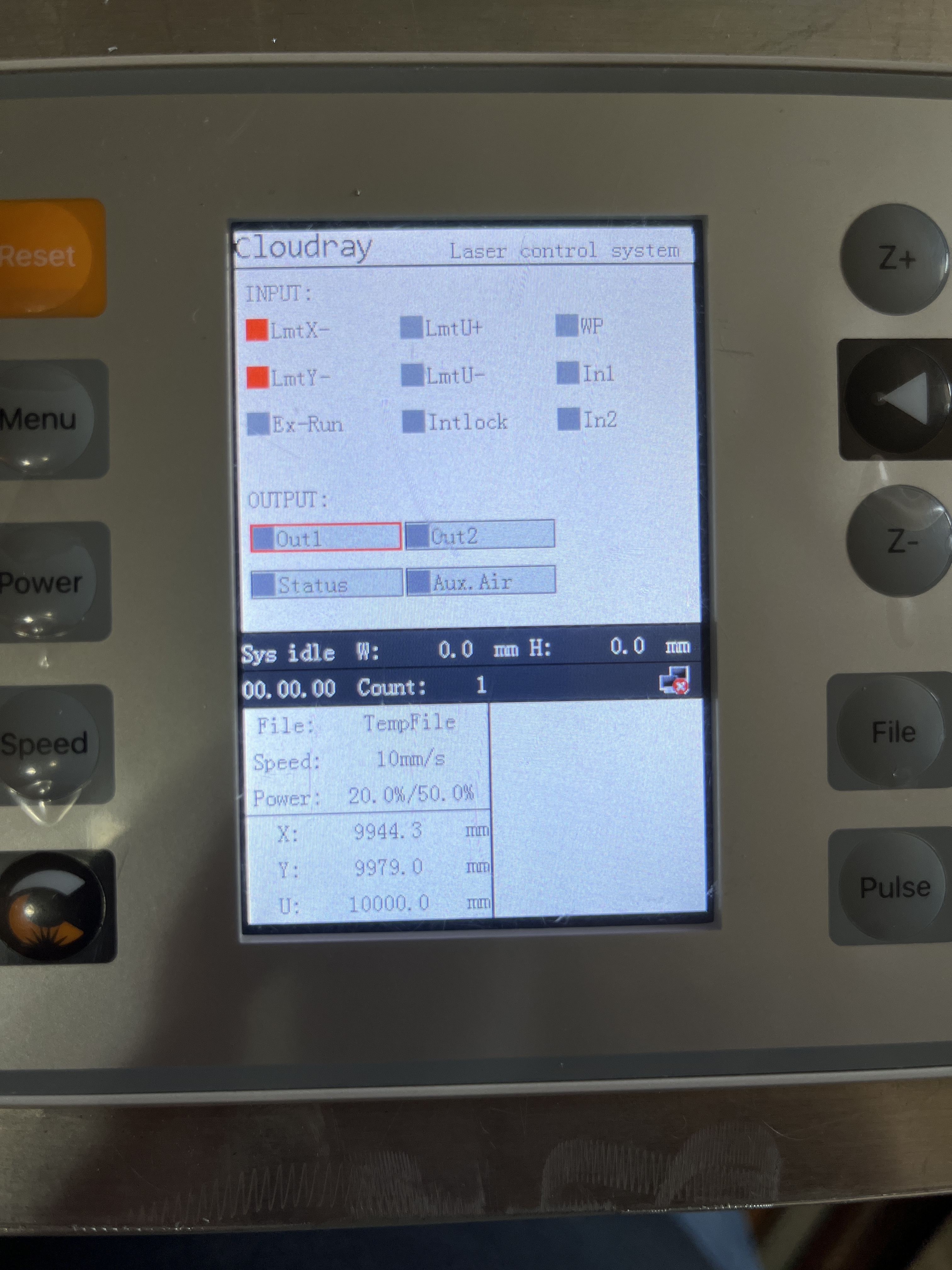
I think the controller will not update the X and Y coordinates until both are homed; the ones on my KT332N stay at 10000 mm.
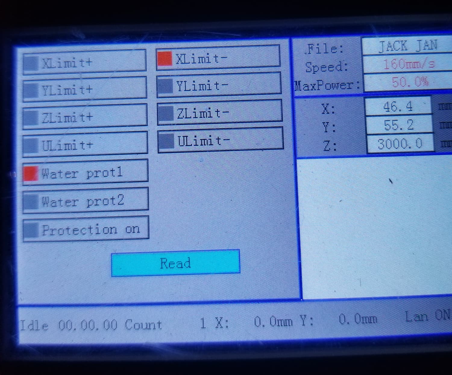
The photo shows the X axis sensor lights up with the laser head near it, so verify that the Y axis sensor lights up when the sensor gets close to its target during the homing cycle.
The controller has a diagnostic screen showing the state of all its input pins. Verify that the home switches light up the appropriate sensor inputs there, too.
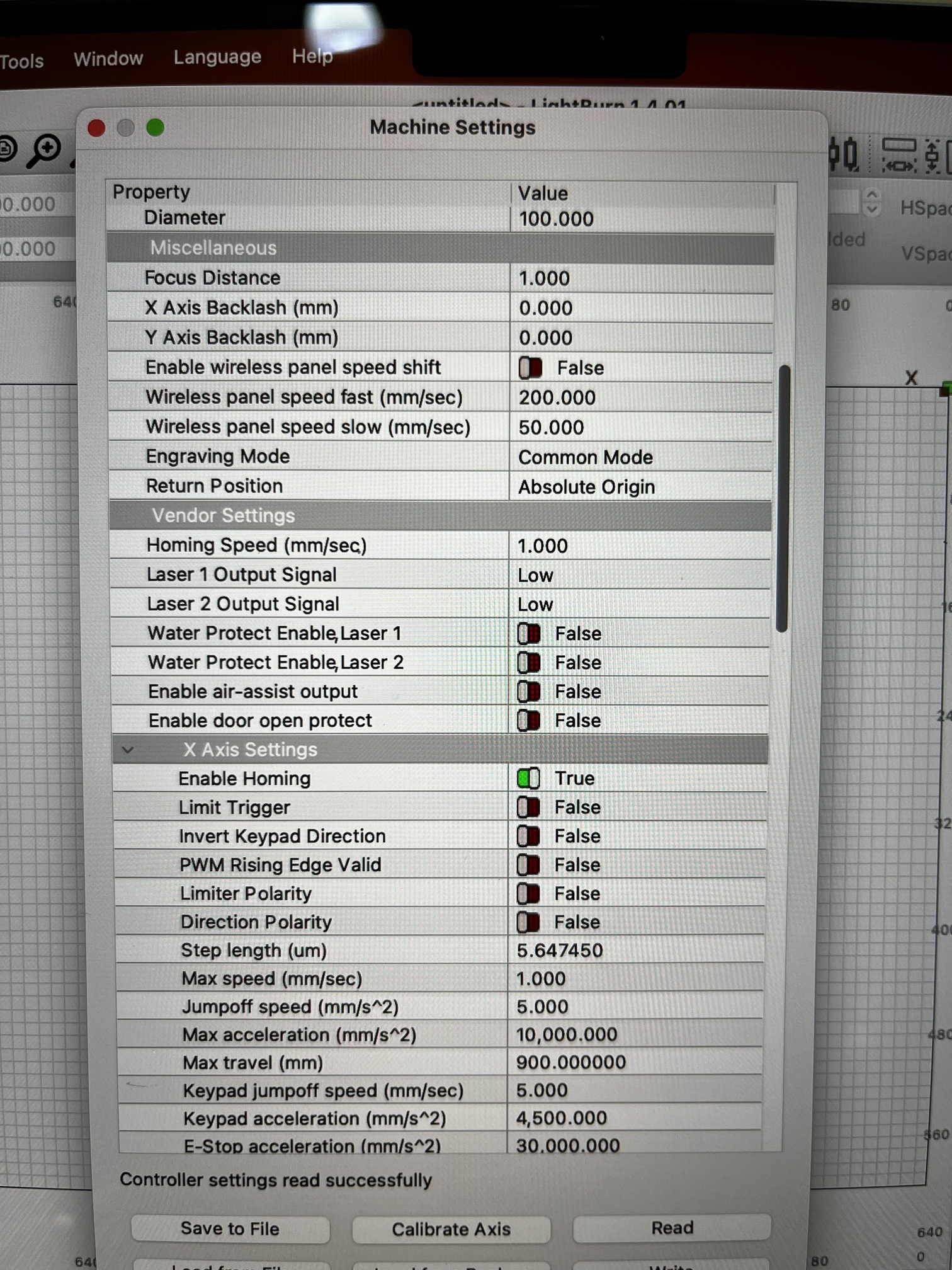
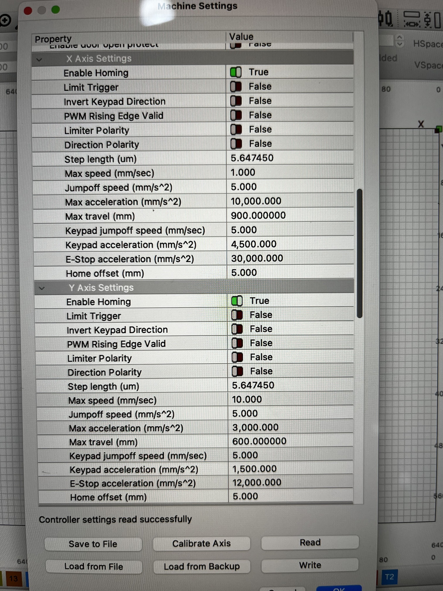
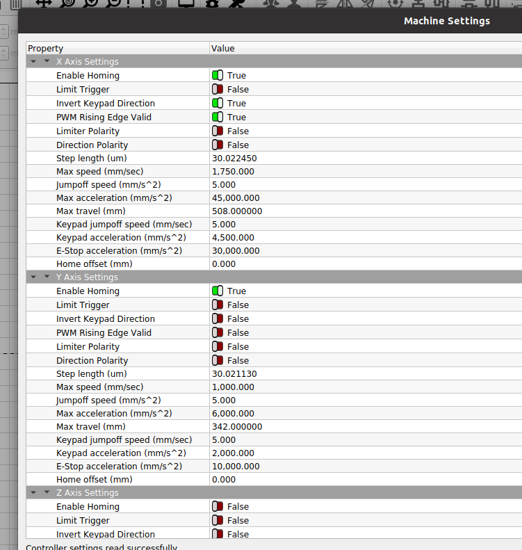
Turn off the Limit Trigger switch in the Machine Settings for all the axes until homing works properly.
The only time the sensors light up is when it makes contact. Both the x and y register on the diagnostic screen.
Did you turn off limit trigger?
As for your home switches, your description is right, so if it’s wired like you stated, then it should work.
Let us know if there is a change with limit trigger disabled… I’m surprised it’s available as the machine only has a U axes limit switch input.
What was your logic for enabling this setting?
![]()
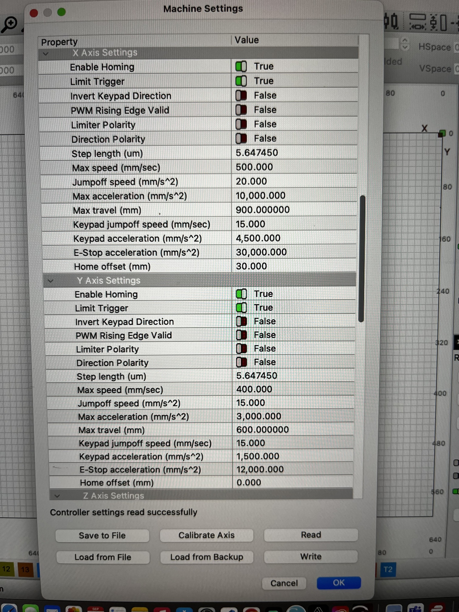
The X Axis Settings show a 30 mm Home offset which seems unusually large, particularly compared with the 0 mm for the Y axis. What was the reason for the large X offset?
The RDC6445 manual has this baffling entry:
Distance from Origin to Hard Spacing: if this axle enables hard-spacing protection, generally this value should be set to be 2~5mm; if it is set to be 0, when this motion axle moves to the smallest coordinate, i.e. 0, this spacing may be validate, which may wrongly triggers the hard-spacing protection and scram the machine. If the hard-spacing protection is not enabled, this value can be set to be 0~5mm.
Set the Home Offset to 5 mm.
I think that describes the pulloff distance from the switch after homing to ensure it is deactivated. Because you had Limit Trigger turned on, that would account for the “scram” after homing.
Turn off Limit Trigger, which seems to correspond to Hard Spacing Protection.
What is the controller’s Homing Speed setting? My controller seems happy with 100 mm/s. If yours is much higher, that might account for some of the smashing.
Turned off limit trigger and set offset to 5mm. Still hits hard. However now it doesn’t throw the hard hit error. See video.
Hard homing
I try to point out that with the dsp or at least the Ruida, the home and limit switches are not the same animal… limits are not examined until after a home operation.
What I’m trying to point out is that the limit trigger is for limit switches, which are not present…
This is mine, notice limit trigger is false on all axes?
Without limit switches, you are telling the machine it has limit switches when it doesn’t… that can’t be a good idea.
![]()
Might be private:
You need access
Request access, or switch to an account with access.
Well, that’s definitely progress.
What is the homing speed set to now?
Set it to 10 mm/s, so that you can watch what happens without so much excitement.
Do the sensors light up when the laser head reaches that corner? Do they remain lit while it’s clobbering the limits?
A while ago, somebody mistook the proximity sensor for Hall switches and used neodymium magnets, which permanently magnetized the cores and destroyed their function. Are you using simple steel plates?
That makes sense. I’ve disabled the limit and only have homing enabled. Still hits hard but doesn’t throw the error code.
I’ve made the video public so you should be able to view it. I have attached aluminum plates to trigger the sensors. I slowed the machine down and used a metal piece to try and trigger it prior to the laser head hitting. The sensor lights up but the laser head continues to travel.
It must think it’s booting or has a different number range than mine…
These are hall effect, so it must be a Farris metal to activate the sensor.
From the video, it looks like the switches are being activated, so you need to follow that signal back to the controller.
Power the machine up and press esc before it hits something. This lets you have machine console control when there is a malfunction… Might have to push it a few times…
Z/U → Diagnosis and see if the machine is reading the inputs… you should have something like this… my Ruida is a 6442g.
![]()
We’re making progress!
That looks much faster than the 10 mm/s I suggested, so if that’s the current setting, reduce it to 1 mm/s. Lower the homing speed until you get this figured out.
The video does not show the Y axis sensor.
Do both sensors remain lit as the head continues?
How much travel (in millimeters) occurs on each axis after each sensor lights up? You may need to measure this by hand with the steppers disabled, pushing the laser head slowly.
After all these changes, get a screen shot of the X and Y axis Machine Settings, as well as the Homing settings, so we all know what’s supposed to happen.
Yes they continue. I slowed the movement down to 1mm and found that the sensor illuminates at 3mm before contact. I only Film the x because it easier to see than the y. They behave in the same manner though.
When it illuminates at the 3mm out mark triggers the LmtX- and LmtY- on the diagnostic screen light up.