I have build my own laser machine with a MKS-DLC32 board to control it. Moving it works absolutely fine but connecting it to the laser power supply seems to be a bit harder than expected.
I cannot seem to find the right pins to connect the machine to. I have bought the powersupply of Aliexpress (the 50W version). https://nl.aliexpress.com/item/1005005730279570.html
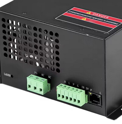
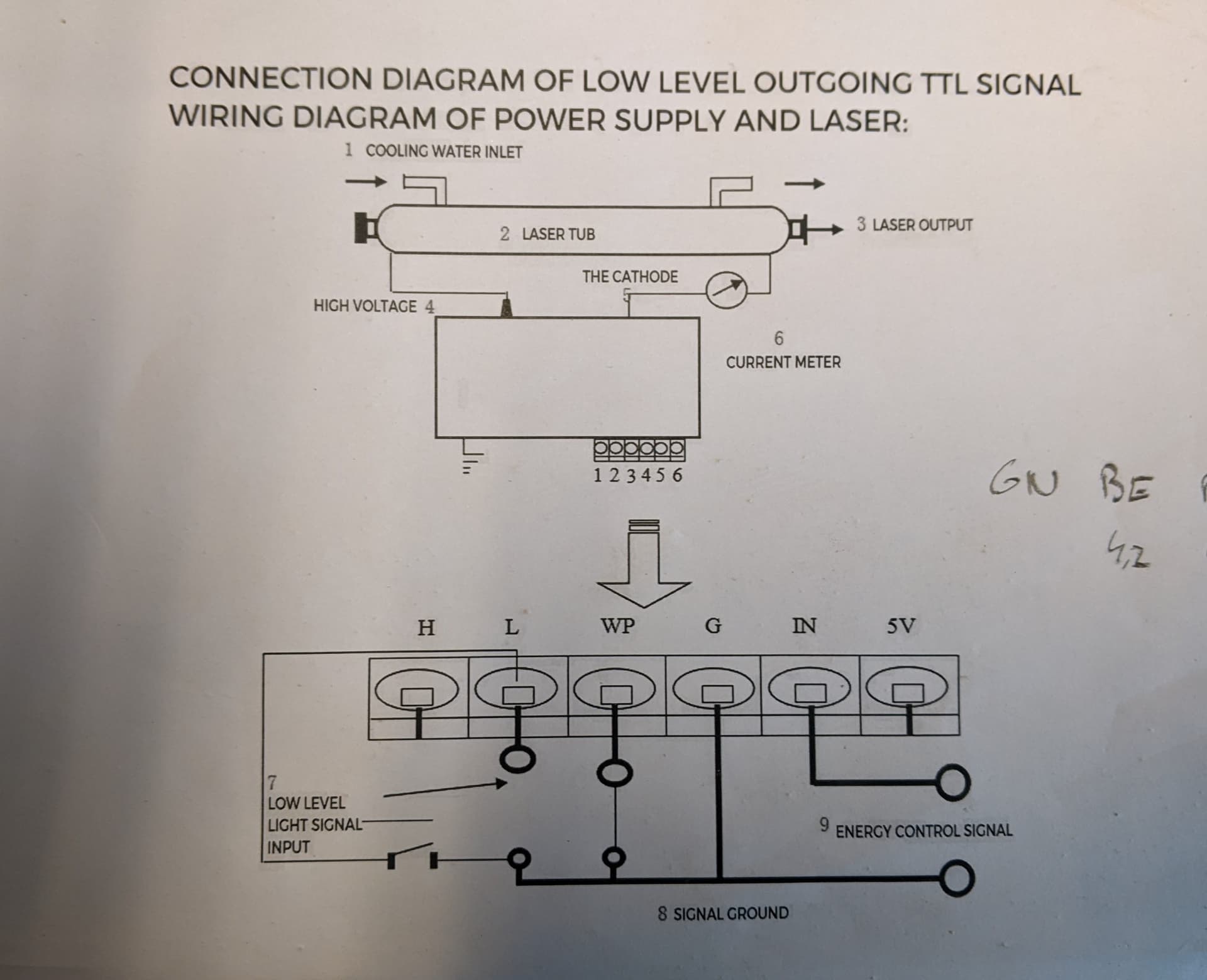
The documentation that I recieved with the supply seems to have a different pin configuration than it says in one of the pictures and on the vevor website.
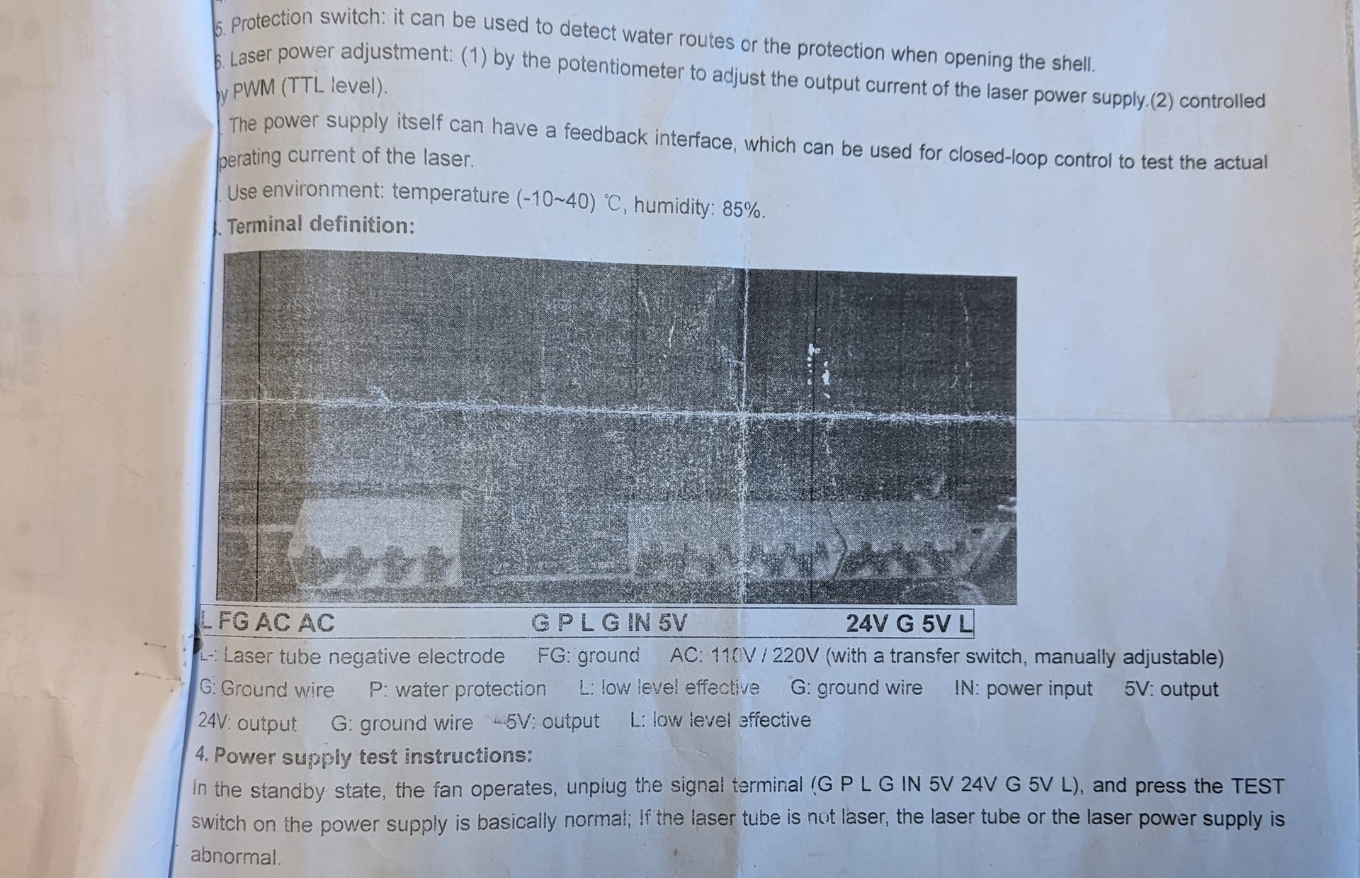
documentation says
L- FG AC AC G P L G IN 5V 24V G 5V L
website says
L- FG AC AC H L WP G IN 5V 24V G 5V L
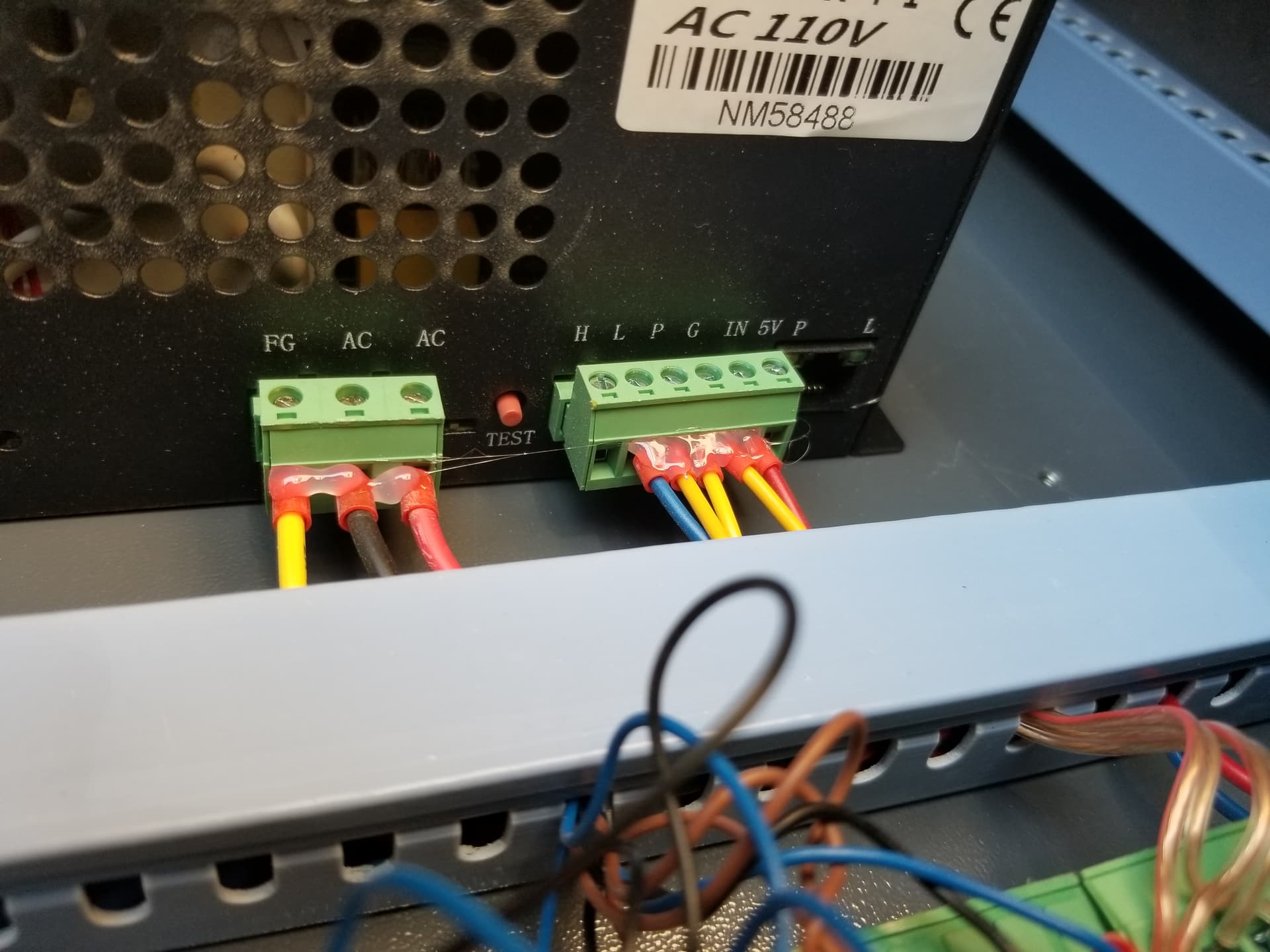
I have measured the pins (the 6 pin connector) and these are their outputs
0 4,2V 4,2V 0 4,6V 5,0V
When I run the board on GRBL-M3 and activate the laser on 20% I get these outputs :
on the spindel output: 2,13V
on the signal and TTL output: 0,25V
I have read through a bunch of similar posts on this forum and have tried a bunch of different solutions all without much result, if someone can help me out that would be greatly appreciated.
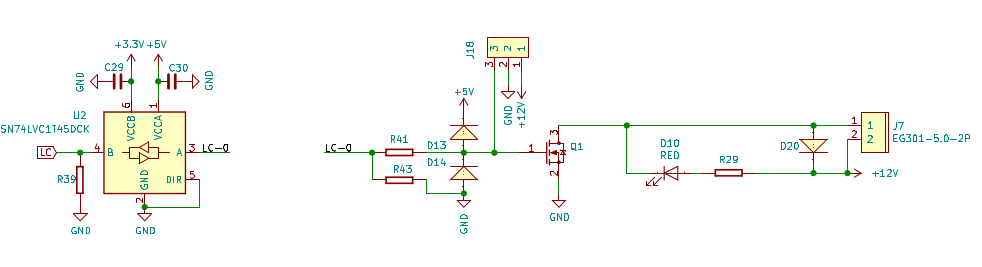
You should not be using the spindle output of the DLC32. The PWM is generated by the cpu at 3.3V and is passed through the 7400 series chip that’s used as a voltage translator so the pwm goes to LC-0 at a 5V pwm. This directly drives the pwm coming out of J18.
If you use the spindle- (J7) it’s only grounded when the pwm goes high and enables Q1 to pull the negative pole to ground. The other pin is just the supply voltage.
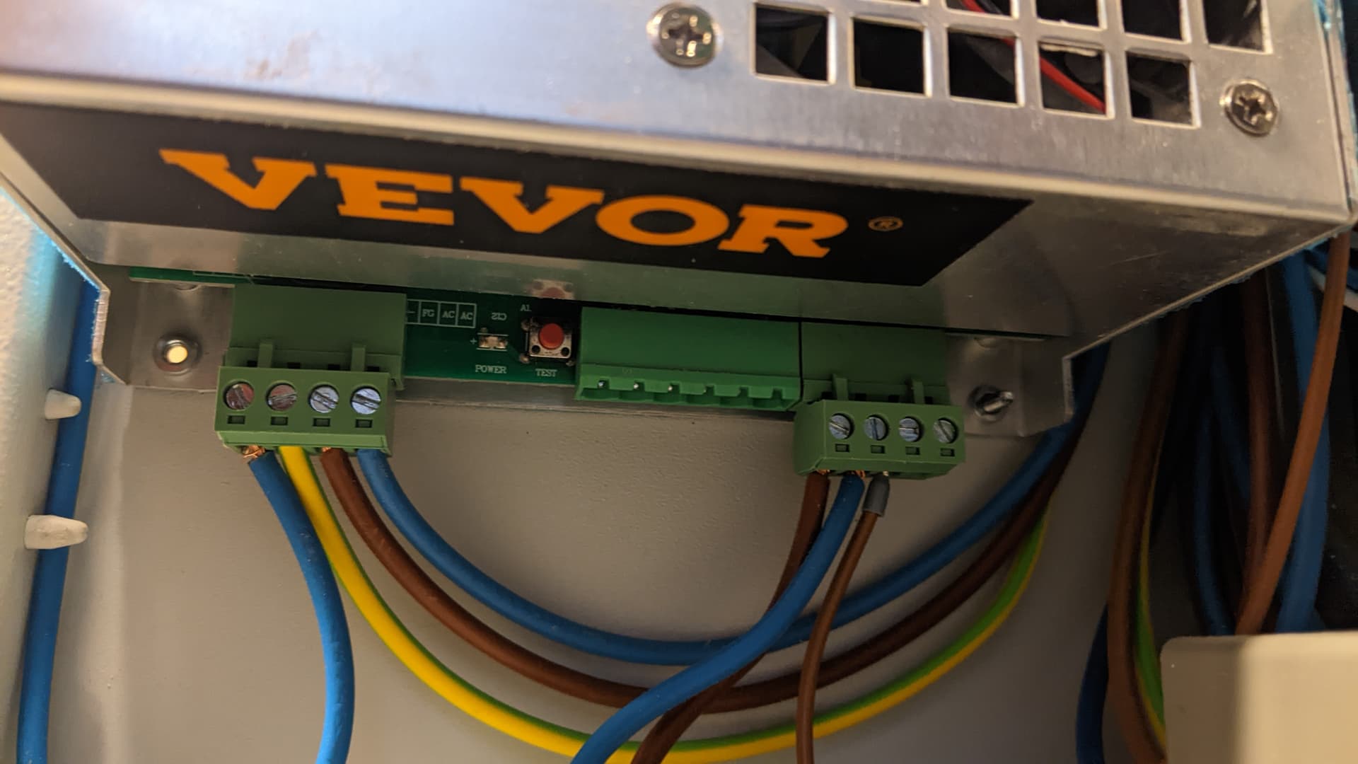
Sadly it does not say anything on the laser power supply itself, it does tell me the pin layout of the two outer plugs but not the 6 pin comunication one.
The lps you’re dealing with appears to be a K40 type lps. This is not the same as the link you posted. I’d use the first one as the pin out since it matches the connectors shown in the photo. I think yours is a type 1.
I had mine setup on my co2… You have to have the P (water protect) of the lps wired to your flow switch or tied to ground, bypass the water flow protection. I would not recommend you bypass this protection… Saved me a couple of times.
I ran L to a console switch to enable the laser, but pulling it low. Then the J18, S (pwm) to the IN terminal.
If you want any electronics to be able to use a signal, it needs to be relative to something. So single signal lines require a ground reference. So yes you need to ensure there is a ground across all components.
Use the pin out for the supply that has the same group types of connectors.
If we exclude mains power, then one lps has a pair of connectors, while the other only has one.