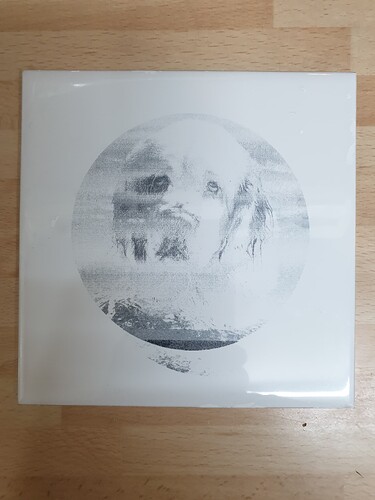
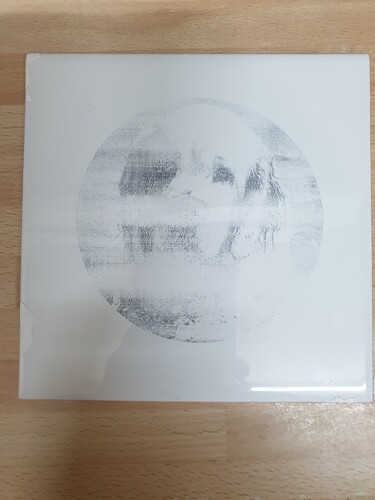
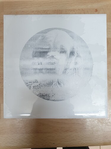
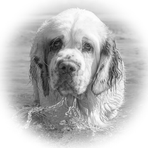
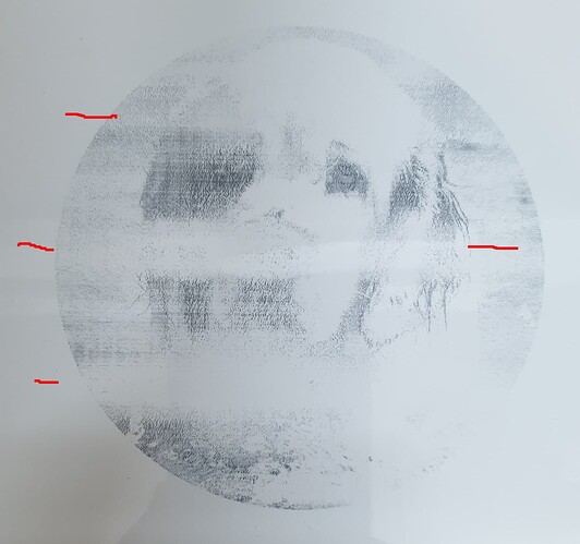
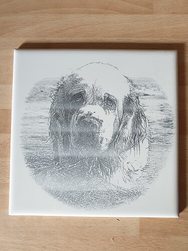
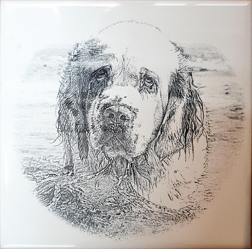
50W CO2 laser with Ruida Controller. I’ve been trying to produce images on white tiles that have been sprayed with titanium dioxide then laser etched. There is a lot of information around and I’ve read what I can, however I am getting a strange issue with striations in the image and I am not sure why! Could it be a too high resolution image and there is memory problems, I don’t think it’s the laser hardware as I haven’t see it on anything else. I have done three tiles so far at 40%, 42.5% and 45% power I have uploaded pictures of the results and the original. Any suggestions please?
Nice photo… and critter…
This looks like an uneven coating… however,
What dpi are you attempting to achieve?
What is the image mode on the layer or dither?
If you can rough out the mixture and how you are applying it to the tile, we might be able to advise you more accurately…
![]()
I am using a spray can for the moment and apply two coats and let it dry. I use dither for the image. It is 254 DPI.
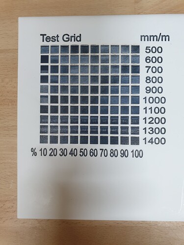
I attach a Test Grid, which I think show it is an image issue, not a machine issue!
I still think your coating is not even… The material test is not very informative… It should go from light to dark… it’s almost monotone across the whole test area… Zoom in and you can see that it appears there is variations in the coat thickness…
Might check out this thread… there are a number of them for ntm and for different mixtures of TiO2.
Some of these use paint with TiO2 being the ingredient, some of us have strived for a less toxic way of doing the same without the issues of paint removal.
![]()
I appreciate that there are more “environmentally friendly” ways of covering a tile, but as I was initially experimenting just to see if I could get it to work, a can was quick and dirty! I spray the tile twice up/down and then left to right. I think it may be more of a machine power/speed issue or even an image black/white/greyscale/half-tone than coating. I’ll continue to play - at the moment there are too many variables and I’m an engineer, so most of PhotoShop is a mystery to me - I can only do the simple things!.
Maybe that’s part of the problem… keep it simple, especially if you are learning how to make it work. Lots of people do this with pretty good results…
If you want to dodge/burn or do something exotic manipulating photos, that is the place for an external software package…
Lightburn has great control over images with better display of what it’s actually going to do on your laser.
You add another pair of variables into the equation if you do work with one product, export it and then import it can induce other anomalies. Theoretically it should work… but there is lots of controls in photo editors that can interfere with the end results… very probably why there is a passthrough option in Lightburn.
I suggest you learn to look at the damage done by your laser on the material and understand what is happening to it…
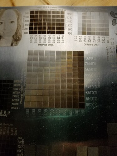
This is from my fiber, but the general idea should apply equally. You can see where the normal variations exist, fast speed, lower power, less damage so not as dark… This took no time to setup using the materials test in Lightburn… Suggest you use the laser tools → materials test
On the other hand, yours shows no variance with the actual test data across the whole test piece.
Your piece clearly show a variation in density across multiple test patches that should be different in a step, not the whole row showing a lack of damage.
All things being equal this would be diagnosed as a mechanical problem, more than likely the thickness of the paint layers…
Sometimes looking at the problem conversely helps you make decisions.
How would you create this if the machine was working… how could you tell the software how to do this anomaly? What kind of hardware failure would cause this?
I’d say no to both of these… although I’m sure there is something in the tube/lps that could happen… but very unlikely.
If you are trying to use grayscale, that is likely a problem with tile… it’s like a printing press, it’s black or it isn’t… it need to use some kind of dither to create the image.
Dpi/lpi is always an issue… Most co2 have a dot size of about 0.10mm, with perfect focus on the perfect material you can do 256 dpi/lpi. I cannot get that kind of resolution on my tiles, on this machine.
There is a limit to what dpi/lpi is feasible… I’d recommend that you watch The Laser Everything video on photo engraving… this video is clear, procedure that will give you the best possible dpi/lpi for any laser with any material… Suggest you spend a few moments and adsorb it.
The last item, you didn’t use the materials generator and your output looks far from what it should be… It looks like there is no variance in the squares… so I wonder about the .lbrn2 file that created it… Is it really doing what you have labeled? Don’t know your skill level with Lightburn and there are not 100 layers you can create…
I still say you have an issue with the coating thickness… Unless your hardware is loose somewhere…
This banding is indicative of an uneven coating…
Good luck
![]()
Thank you for taking the time to produce such a comprehensive reply. I am learning a lot! I didn’t know that greyscale wouldn’t work, so I am back to various dithering. It seems a lot of the example are using LED lasers where I have a CO2, so it is not a simple translation.
I’ve done a few test samples with that picture at different speeds, powers and types of dither. My next challenge (I suspect) is getting that even coating!
Peter
I’d suggest you try the materials test instead of building your own… I don’t know how you did it… I’d like to ensure it’s right if I’m basing settings from it.
![]()
Hi.
I’m no expert with lasers or Tio2 fusing with them by any means, but a few things come to mind from the materials side of the issue You’re facing.
First is the quality of the Tio2 spray, and the second is the surface properties(/quality) of the tile.
While the uneven application of the Tio2 coating @jkwilborn suggested could well be at least a part of the issue, that -alone anyway- doesn’t quite explain why there’s variation even inside the individual boxes in Your material test.
What did You clean/wipe the tile with before applying the Tio2 spray?
Do You have access to some other tiles from other firing batch or even from another manufacturer?
I’m askin this because from the pics of Your lovely dog, it almost looks like there might be some sort of protective wax or firing residue on the surface of the tile, but it’d be a freak coincidence that You’d lasered three tiles in exactly the same orientation.
And the material test piece doesn’t show the same horizontal lines.
Some of that strange behaviour could perhaps be explained if the Tio2 is for some reason permanently separated from the solution, and the pickup tube on the rattle can draws different concentrations at random.
That can be tested by applying the coating at an angle.
If the shady areas follow the direction of the application, then it’s the spray or something in the application method.
In order to test the tile surface as a reason for that indeed strange behaviour, I’d suggest that You do the test with vertical lines instead of horizontal, and also rotate the tile on another test.
IMO quite the opposite.
Because…
Excactly.
And this one for some odd reason does not.
The text however looks pretty good and uniform, to me anyway.
@puffernutter , what’s the power setting of the text?
I don’t see it as monotone, there’s quite a lot of variation as I see it, for some reason there’s even quite strong tonal variation inside individual boxes.
There’s also good -or at least IMO passable- black/dark (10% 600mm/m for example), and decent light gray (90% 900mm/m) box, just not where one would expect 'em to be.
As can be judged from those two examples, that material test result does make very little sense, that’s absolutely true.
The material test however IMO tells that there’s several issues that should be adressed, preferably one at a time.
While there’s plenty of even quite drastic differences between different types =wavelenghts lasers when it comes down to cutting and marking various materials, fusing Tio2 onto glass/glazing can AFAIK done with pretty much all of them.
There’s obviously parameters and nuances that must be adjusted as the best possible results are usually the goal, but as You can see from Your test pieces, some Tio2 will always fuse.
That would be my suggestion as well.
Especially as IMO there’s probably several separate issues at play, judging by the test pieces and the material test.
When, and only when the material test shows the intended linear light (even white) to maximum (black) tonal variation result, then You can tackle the whole picture manipulation part of the “laser marking a glased tile” for the best possible results.
Good luck from me as well ![]()
Regards,
Sam
More trials, more fun. This is getting to be an interesting engineering investigation!
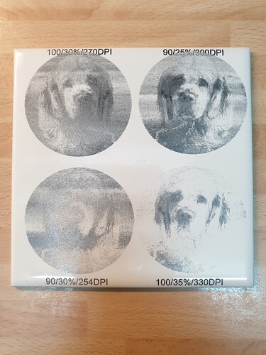
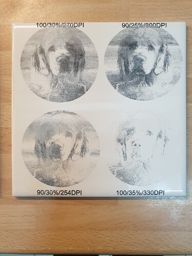
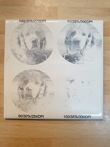
I have produced a test tile with 4 images on at different speeds and powers. I then varied the amount of paint I put on, either one coat, two coats or three coats - it gives some interesting, if not non-intuitive results!
Uploading: 20230801_210727.jpg…
Uploading: 20230801_210732.jpg…
Processing: 20230801_210738.jpg…
The lettering (out if interest) is 13.3mm/s and 100% power.
The one with three coats gave the worst result and the one with one coat is the best so far and using 90mm/s, 300DPI and 25% power.
I know my focus is OK as the laser/engraver is new to me and it was cheap as it did not have the laser in it. So I fitted it and set it up to target correctly and also did a test piece to know the optimum height.
I haven’t found the graduated image in the YouTube clip (yet) so I cannot see how close my lines are together, but trying 300DPI seems to have a reasonable effect.
I will move to the “home made Titanium Dioxide solution” as I now have white glue and food grade powder. So it’s probably better if I start mixing that up and using it otherwise all the results I get will be negated when I change - ho hum. What fun!
There is more erratic variations in his material test on one line as the whole tile.
This is one of three things…
- software isn’t working as predicted
- machine speed is changing
- laser power is changing
- the coating isn’t consistent
I know the one I’d target… With text this can be easy to miss, less likely with blocks.
@puffernutter none of your photos uploaded… it can be slow, so wait for each to complete before continuing. So we can’t speculate on them directly … ![]()
I have a China Blue 50W from OMTech… it was incapable of producing a dot any smaller than ~0.10mm and that took me a bit to figure it out… with that, the best you can expect is that interval (254 dpi/lpi). The only way I could reduce the dot size was to go with a compound lens…
While you dial this in… I suggest you use an interval of 0.20mm (127 dpi/lpi). This gives you some slack to get the coating/setup correct. It also gives you a good visual when you examine it under magnification. If you can easily see the scan lines, you can see more clearly what is happening at the material level.
I may have mentioned this before, but the thicker the coating the lower the resolution… Laser Bond Technologies (they make LBT100) advise the same thing…
If you are having fun, does it matter?
![]()
I don’t claim to be an expert on this, but from my personal earlier lackluster results, this looks like an application issue to me. In your earlier post, you state that you put on one layer, let it dry and then apply the second layer(s). Are these all applied in the horizontal orientation, or do you apply one layer horizontally and the second vertically. Based on the most recent examples, it looks like the three coats looks better than the two, which looks better than the one. In all three, the application still does not look evenly applied to me. This can be a result of the speed of motion as you apply, room temperature, angle of application etc. Applying two coats, one horizontal and one vertical, for EACH application helps offset this variance. If that is what you are already doing, please ignore my input.
Hello, all advice is welcome and is studied. I thought that the third coat gave worse results unfortunately, but thinking about it, do I need to up the power with more covering. It is getting better, but I do get unevenness, which is really annoying as I don’t get that on any other engraving (wood, glass etc.) so I don’t think it’s a machine hardware fault, I suspect it is the way the tile is covered
I am getting close, but as yet “no cigar”
Thinner the coat the better the resolution and less power required…
Unless you are running with short lens, capable of <0.10mm, then anything above 254 dpi/lpi will cause other problems. I can only consistently get below 0.10mm with a compound lens…
I think my 4" has about a 2mm kerf, so I’d suggest restraining yourself to <254 dpi/lpi… I’d really suggest 127 dpi/lpi until you get closer…
Try lower power also… Seems to me, I’ll have to look, but I was using around half the power of your settings… It looks like you’re blasting off your coating…
I agree with most of them that the coating isn’t consistent.
![]()
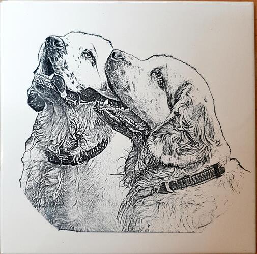
Happy with the power now and this is two coatings of the spray can. I’m sure it will all change when I move to home made mixture! Anyway, I am happy with these and they are true to the originals
Thanks
Peter
They look good, but I think you can do better by moving the grayscale area a little more towards the white end… Try to get a little more details in areas that are almost white…
If it’s pure white in the photo, it’s difficult to handle… You’d expect to see some details to make the top of the head more within the gray range…
A friend lost his daughter and the only photo I have is a very poor quality selfie… Deep black and white areas are almost washed out. I used a photo editor to dodge the dark spots and burn the light spots… So I’ve been struggling with that image, although on slate… same issue…
Good luck
![]()
This topic was automatically closed 30 days after the last reply. New replies are no longer allowed.
