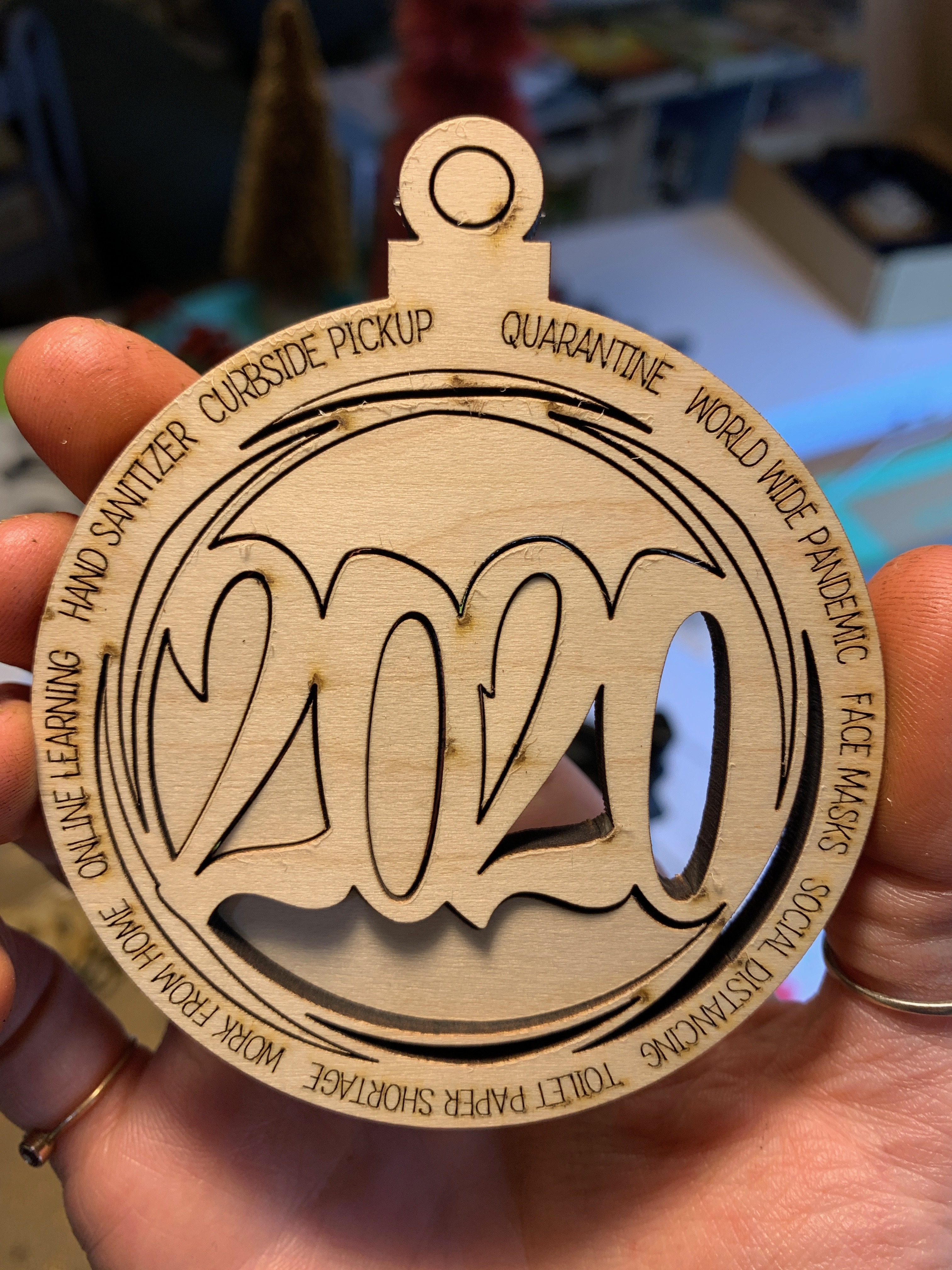
Question from a newbie. I am trying to perfect my cut on this ornament, and when I look at it I can see that all the burn marks show up on the ornament. (the spots where the laser started/ended each of these cuts). Is there a way to do something with the nodes so that the burn marks where it starts/stops end up on the chads/pieces that are discard? I tried playing with the offset/inset, but that just made the charring worse. My theory is it did that b/c the laser just ended up concentrated in that general are of the cut for longer (130 watt laser) so it ended up creating more damage instead of helping.
If the only solution here is to use the inset/offset, can I specify which side of the cut it leads in from or does the software algorithms always choose that?
It looks pretty thick your material, can you mirror the ornament itself and burn it from the back ?. You will of course get an extra workflow but if the result gets better it is worth it.
On the other hand, I think your result is fine enough considering the thickness and you need to sand the surface a bit anyway.
Thank you for the ideas. I hadn’t thought of sanding after. I prefinish two coats of varnish then lightly wipe off the residue. Which isn’t working too well b/c to get the char off I am removing the finish. But I really like pre-finishing from a time saving perspective. I suppose if I put the honeycomb in I could lay the whole sheet down, cut, flip them in place, and then engrave to finish them. (sounds like a bit more work though! ) - hoping somewhere in the advanced settings is a way to dial in where the cut is angling from , or is there a way to have it start at much lower power? I know that there is a min/max power but think that just applies when it slows down the lower power kicks in? Hmmmmm. So many questions!!!
The char is ejected smoke coming out the front before the cut has gone through the wood. The laser fires and begins to move along the cut, and for just a moment it hasn’t gone through yet, but it has made a short trench behind it, and the smoke ejects that way until it punches through.
The only way to steer it where you want it would be careful use of ‘Lead in’, so the leads were always placed in the offcut. Light sanding, or a bit of alcohol on a cloth will remove the soot easily.
Thank you. With the lead in is there a way that I can visually see in the program (besides print preview? or is it even there?) where the lead in is coming from/going to and can I adjust it to point the direction I want? I ask b/c sometimes a design might have a bunch of separate cuts in the design and so when I make a lead in change in the one place it causes unintended consequences in others and I’d like to be able to visually see where it’s all going and adjust/control it before I cut?
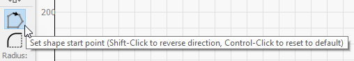
You can only see lead in/out in the preview. You control where they go using the ‘Start point edit’ tool.
Lead in is set as a length, an angle, and a type. If the angle setting is negative, it will run from inside the shape. If it’s positive, it will run from the outside. In either case, there needs to be room for it - the software doesn’t auto-place them very intelligently.
You can only see lead in/out in the preview. You control where they go using the ‘Start point edit’ tool.
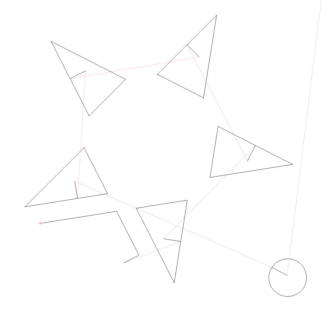
Hi Oz, I’d like to report that sometimes (that’s confusing - I can’t replicate, but sometimes occurs) when you change the direction, the preview still draws the same direction, even worse - it sometimes doesn’t register the whole change of the starting point.
So for anyone else having a slooooow day, turns out the boxes do just what they are labeled. I was confused by how close the in/out were to the other options (angle/length).
Can you please verify: am I correct in assuming that you have to set the same lead in/lead out behavior on a layer, there is not a way to set a separate set of settings for lead in and lead out?
Also, it looks like there is only a -90 to +90 angle range, is that correct? I want to start my cut in this corner, but it looks like these is no way to do it b/c I would need a 135 degree angle. Or am I missing something?
A 135 degree turn would cause the laser to effectively stop, which will cause some charring at that point, reducing the effectiveness of the lead in. Add a point to the middle of one of the sides, and put the start point there so the lead-in starts there, and you won’t need the extreme angle.
We have a task in our bug list to make the auto-placement of these smarter.
Thank you for that clarification, I think that makes sense - I am getting a bit better at it, figuring out which side of the shape to add the start to/adding more layers for different parts of the cut outs… ! Which of the settings in cut optimization override the lead in settings? (or are none of them “supposed” to?)
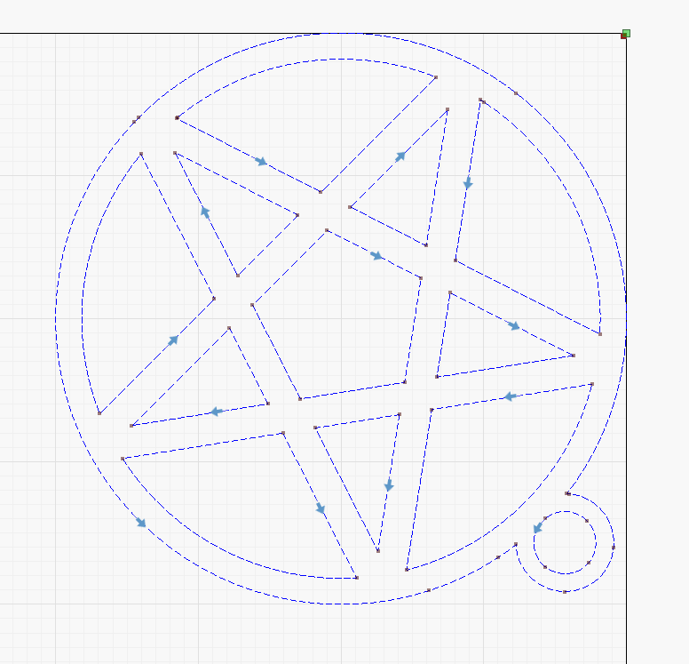
The source lbrn is there: pentagram.lbrn (35.1 KB)
I see I have “choose the best direction” optimization on, butthis should apply only for “automatic chosen” starting points (grey arrows), not for the manually managed (blue ones). Am I right?
You’re right, it’s supposed to respect it. There was one spot that wasn’t checking for the forced start / direction, and that is in the ‘Reduce Direction Changes’ code - if you turn off that optimization it will keep your start direction. I’ve fixed the bug for the next release.
Thanks for all your work at optimizing this awesome program. As a former software coder myself I know how one change cascades into other areas and what “fun” that can be from a management perspective. On the subject of upcoming bug fixes is there any news on when the issue with low/high air not being respected when sent to the Thunder if you use start instead of send will be addressed? Is it already addressed in upcoming release or is that one proving more pesky?
It’s not something I can fix, it seems. If you use ‘Packet/USB’ as the communication method instead of using ‘Serial/USB’, it behaves better. I think their custom firmware might be getting a partial packet at the start of the transmission and getting confused, but that’s a guess.
Using packet based comms prevents that, but it’s not an option on MacOS because you can only install serial OR packet based drivers for the device, but not both, like you can on Windows. If you’re on Windows, click ‘Devices’, then double click your laser, click Next, then choose ‘Packet/USB’ as the communication method. Click through to finish, and try that.
 ) - hoping somewhere in the advanced settings is a way to dial in where the cut is angling from , or is there a way to have it start at much lower power? I know that there is a min/max power but think that just applies when it slows down the lower power kicks in? Hmmmmm. So many questions!!!