Downloaded a dxf of this fun toy, loaded to lightburn and counter rotated one disc and it couldn’t be any clearer how this thing works.
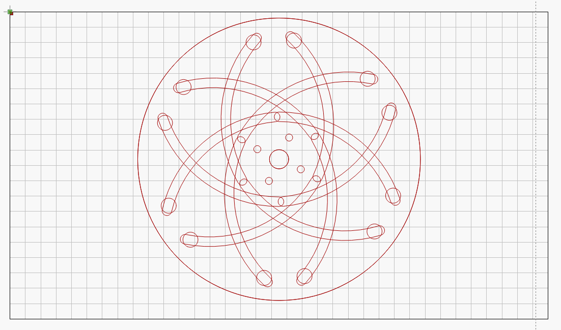
Me like!
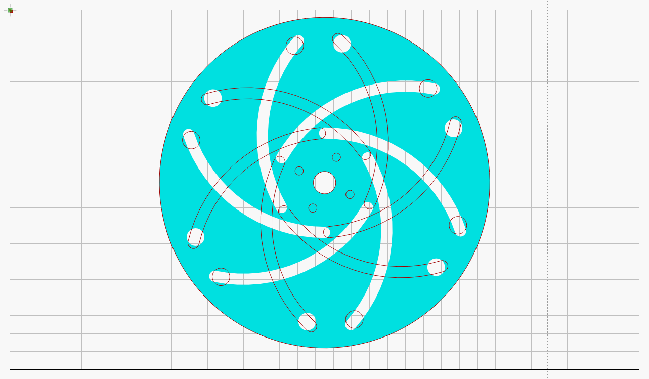
Downloaded a dxf of this fun toy, loaded to lightburn and counter rotated one disc and it couldn’t be any clearer how this thing works.