I´ve made several test decreasing line interval from 0.01 to 0.001 and the result is the same.
**Note: without rotary tool, the cutting and engraving in the machine is normal, no issues.
The steps per rotation I´m using for a 77mm object diameter is 12,697.12
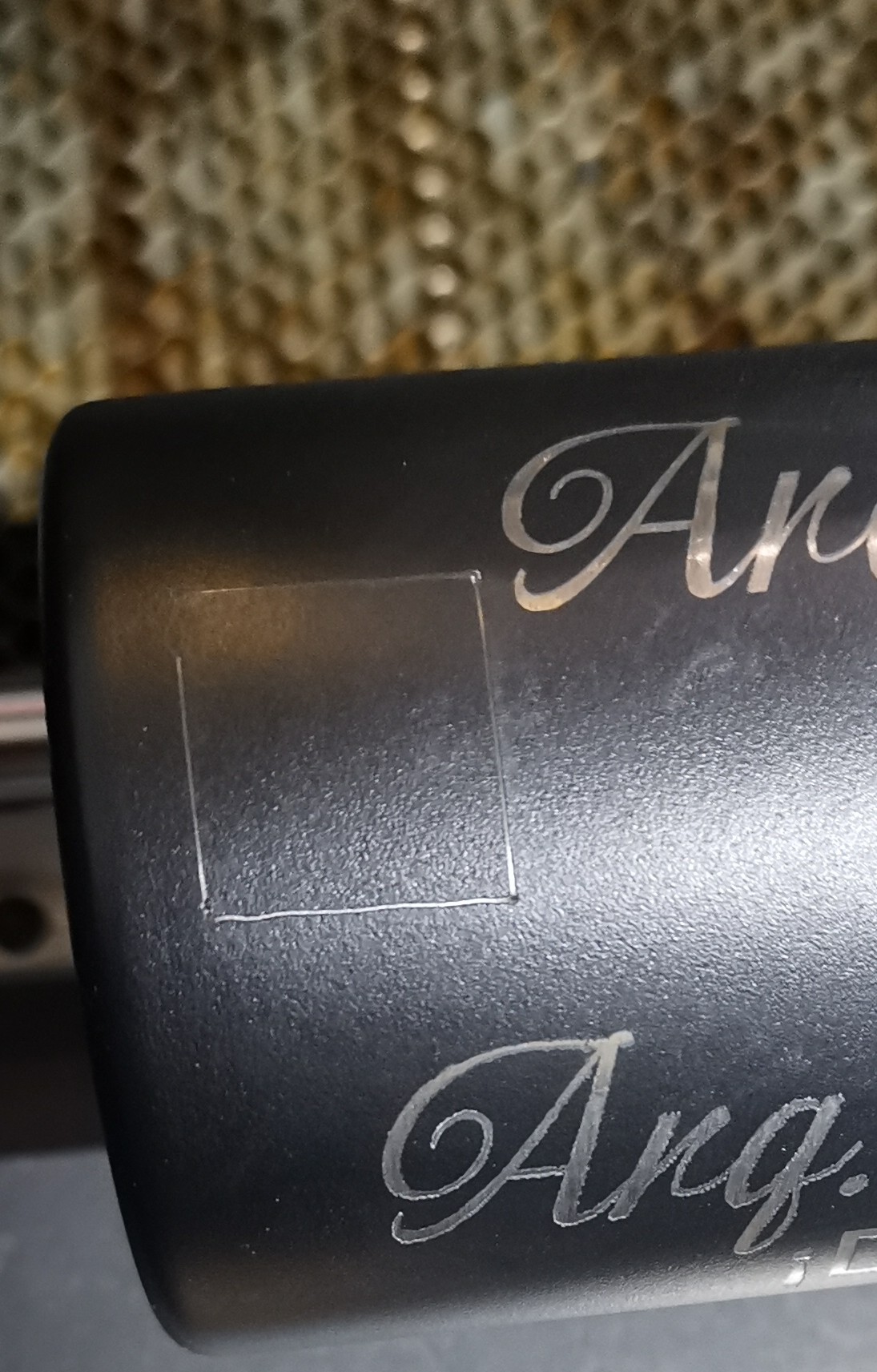
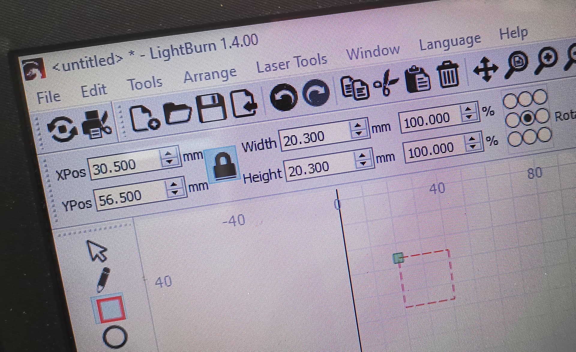
**Note: when I create a square 20x20mm, the height is correct 20mm, but the width always have a difference of -1mm (19mm instead 20mm) no matter if it´s a cylindrical or conical tumbler.
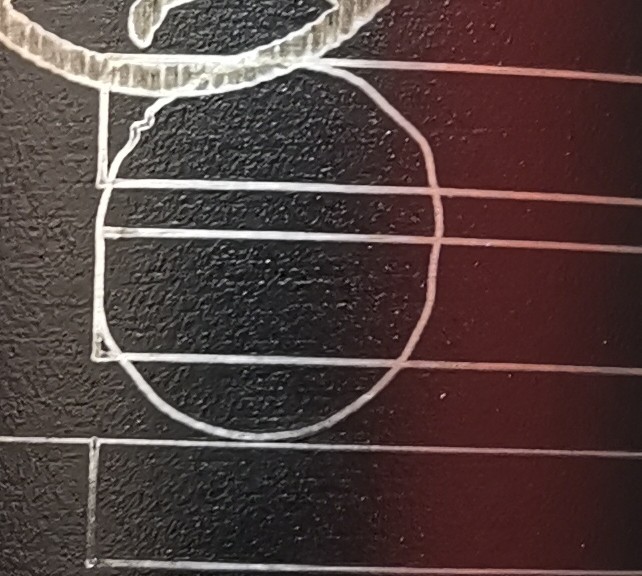
What I realized while making tests is that in certain position, what supposed to be a straight line, it makes like curves
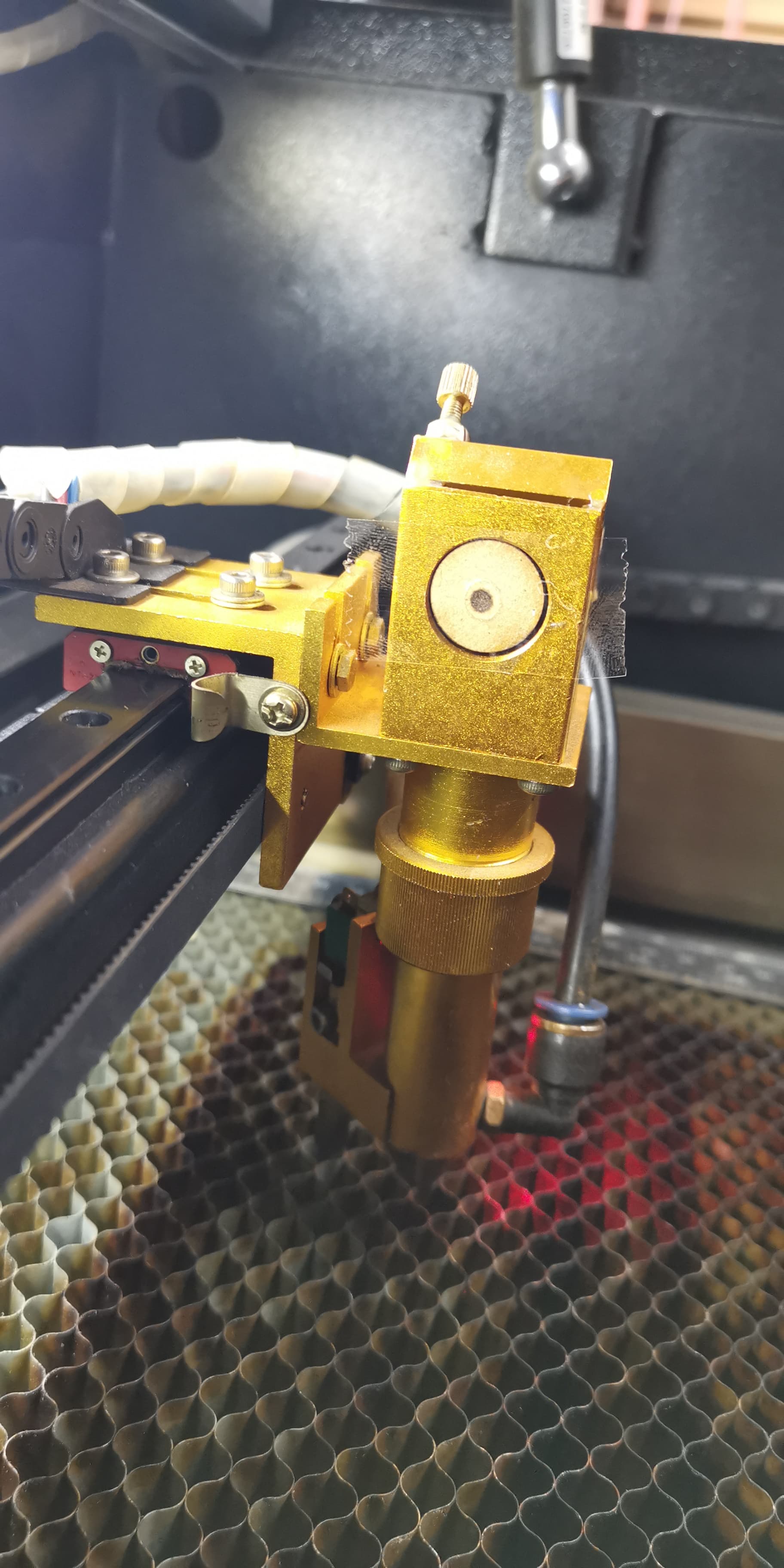
Note: I removed the chuck rotary cover to check if the pulleys spin freely and it wasn´t any problem (clockwise and counterclockwise), but I noticed when the rotary is plugged in the laser machine (turned on) it feels like small “vibration” when I spin the chuck rotary head with my hand. Not sure how to explain it. That feels like if the pulleys had grains of salt or something like that and couln´t spin freely.
Note: Look at the last picture, in the upper left corner, the laser missed a segment of the square.
I keep reading and making tests, but It´s been a long time since I bought this tool and I can´t resing to this won´t work.
Any help would be very appreciated.
Thanks for your response. When refer I did spin the chuck rotary head with my hand I meant powered off. I did it when I removed the cover to check if everything were ok with the pulleys. I´ll take a look at what you´re mentioning, I´m not familiarized with electrical stuff.
That crunchy feeling is normal: stepper motors have rotors with teeth surrounded by permanent magnets, so you’re moving the teeth through the magnetic field.
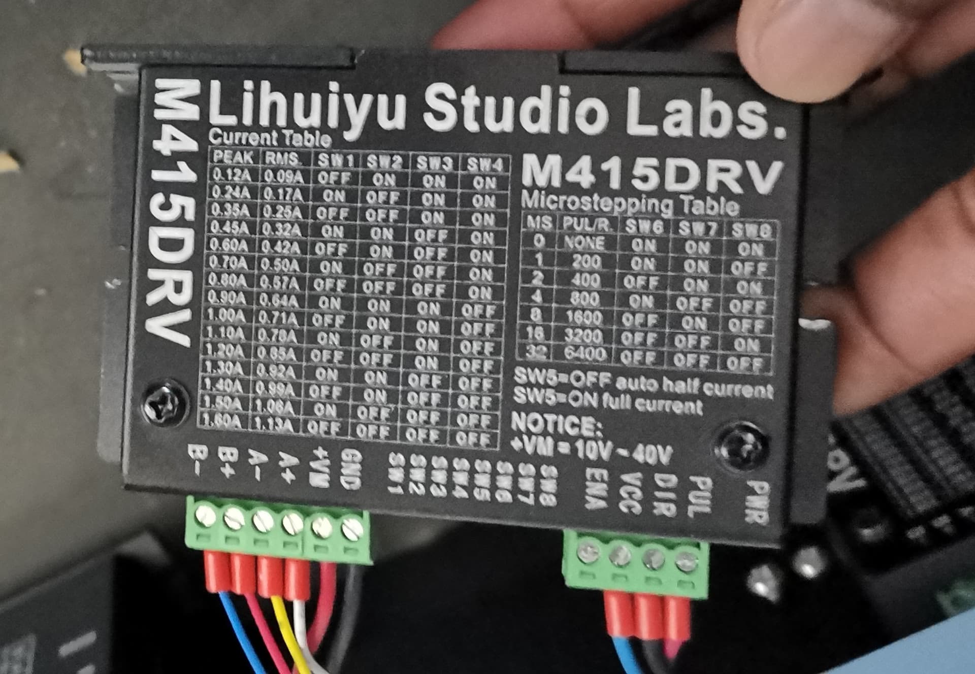
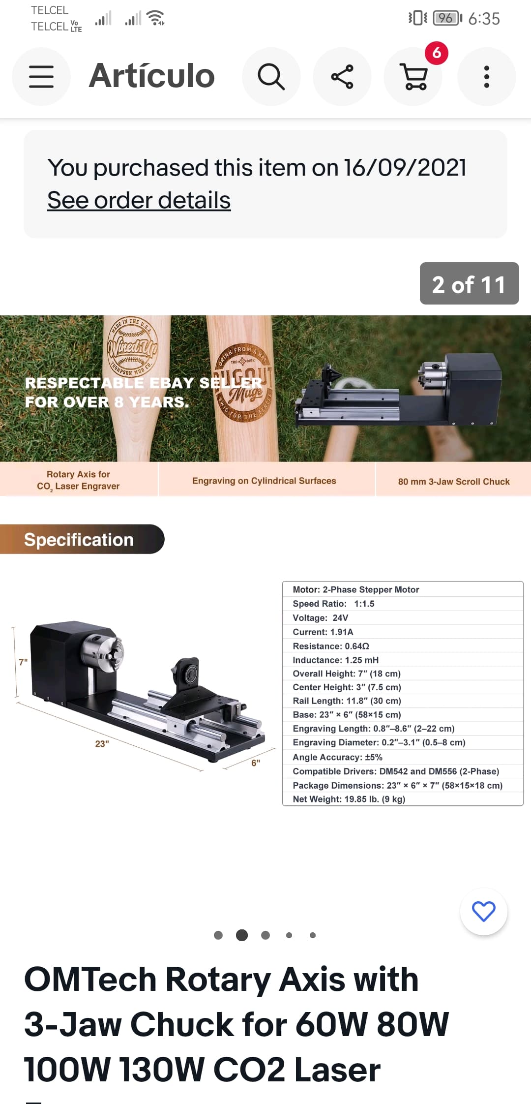
That will be a fixed number, because it’s controlled by the stepper driver and the pulley arrangement. The description you included shows a “speed ratio” of 1:1.5, although it’s not clear whether it steps the motor speed up or down.
The stepper driver requires 6400 steps to turn the motor one revolution, which is fixed by the switch setting on the driver.
If the smaller pulley is on the motor and the larger pulley is on the chuck, then the motor turns 1.5 times for each chuck revolution, so it has 9600 = 6400 × 1.5 step/rev.
If it’s the other way around, then the chuck turns 1.5 times for each motor revolution and you have 4266.67 = 6400 / 1.5 step/rev.
You can confirm the ratio by counting the teeth on the belt pulleys, assuming they used an ordinary GT2 toothed belt. Divide the larger by the smaller and you should get 1.5 exactly.
Because it’s a chuck rotary, the step/rev value will be the same for all objects, regardless of their size. When you enter a mug’s diameter (or circumference), LightBurn then calculates the “distance” required to map the design onto the mug.
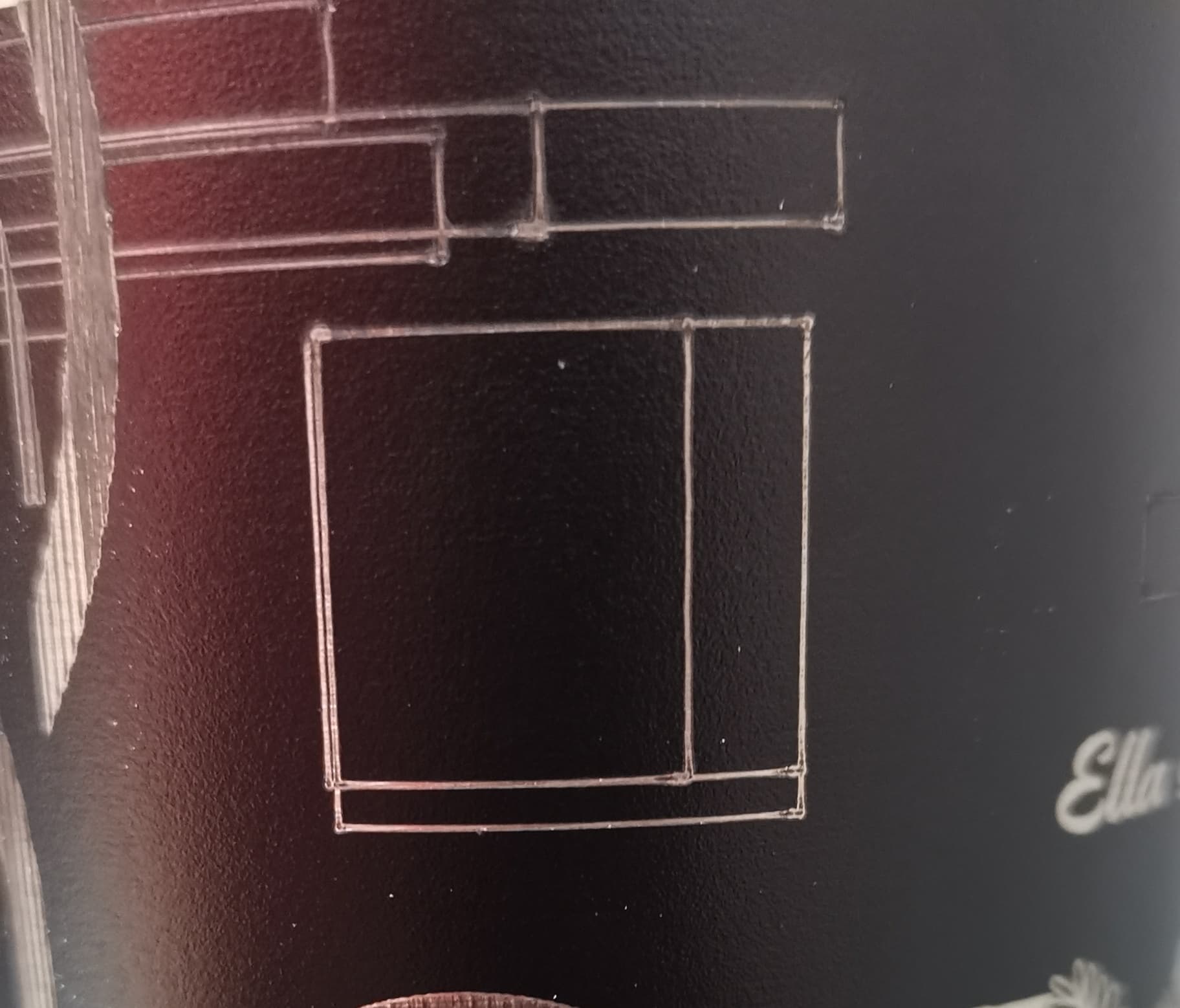
I did it and despite it seems the tool is working better, the main issue still remains. Deformed shapes. This test was made to a skinny tumbler 75mm object diameter, 14,285.71 steps per rotation, SW1 through SW4 OFF, line interval 0.06
Now that you’ve got the motor’s attention, I think you’re looking at backlash in the chuck drive: anything from a loose setscrew holding one of the belt pulleys on the motor / chuck shaft to a really slack belt.
You may also be driving the chuck too hard, with too much speed or acceleration.
Save the current machine configuration!
Then reduce the chuck speed and acceleration by a factor of two. You must also reduce the power (PWM) by about a factor of two to compensate for the reduced speed.
If that improves the results, you know which way to continue tuning.
Once you get that set,save the machine configuration so you can switch back and forth easily.
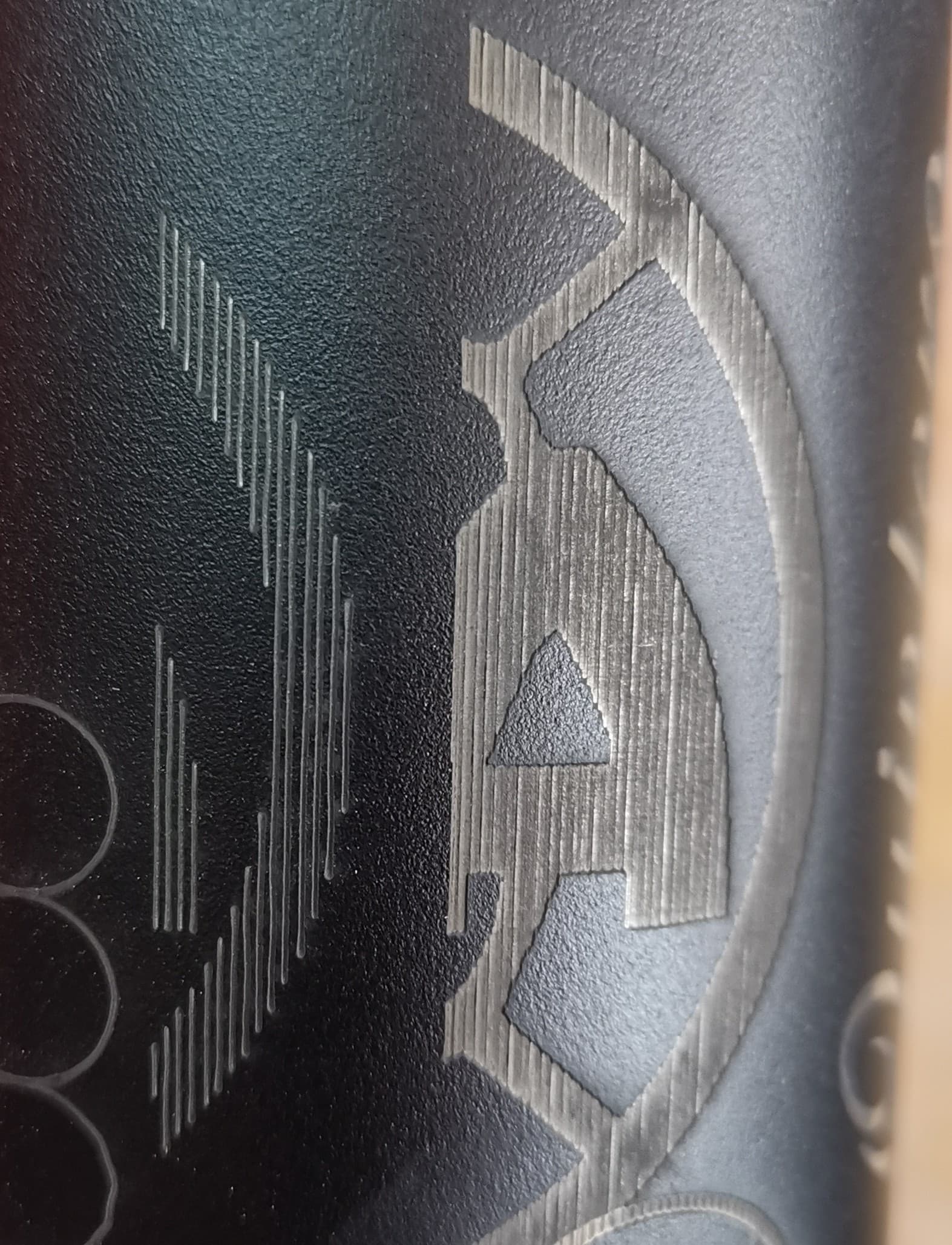
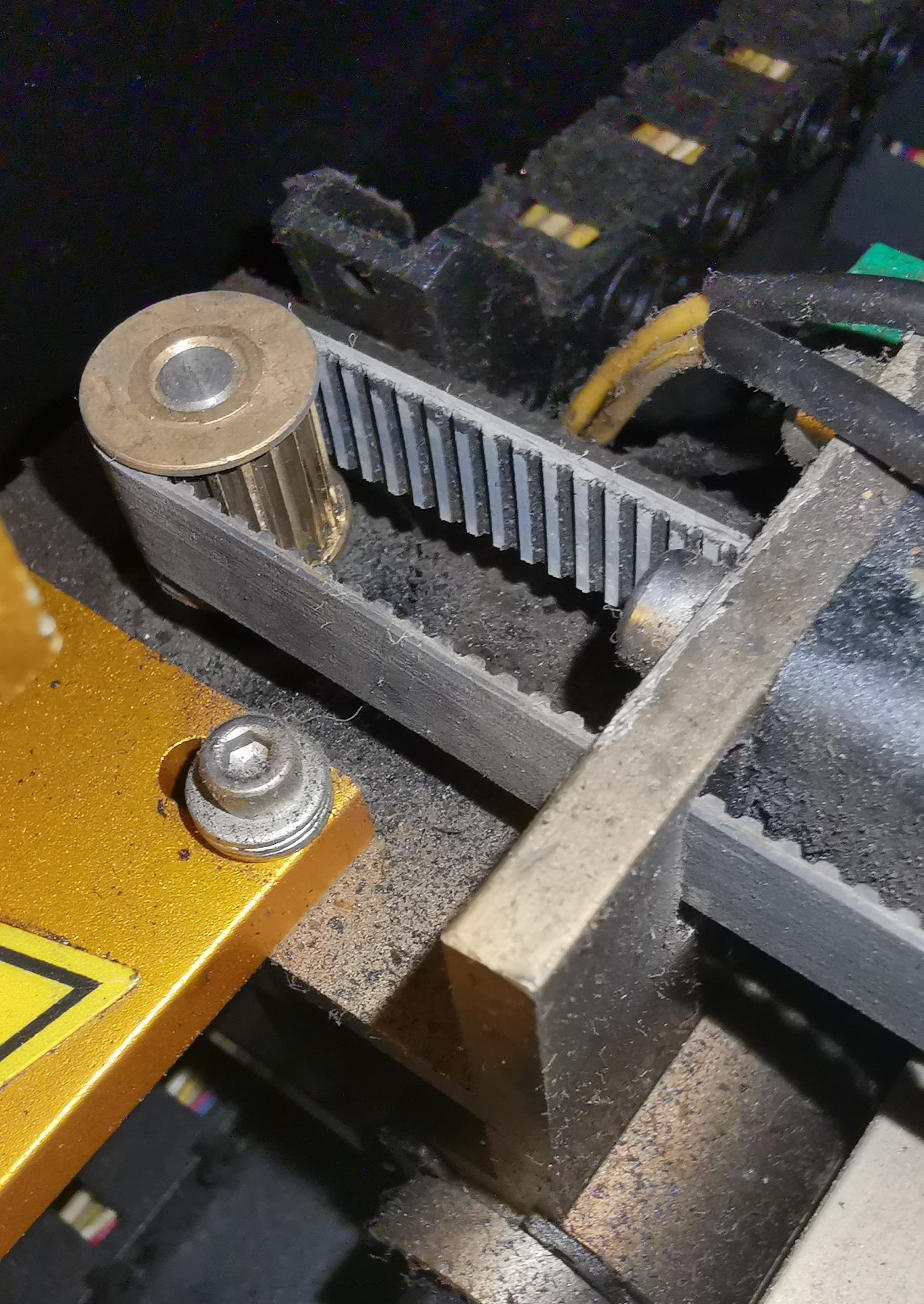
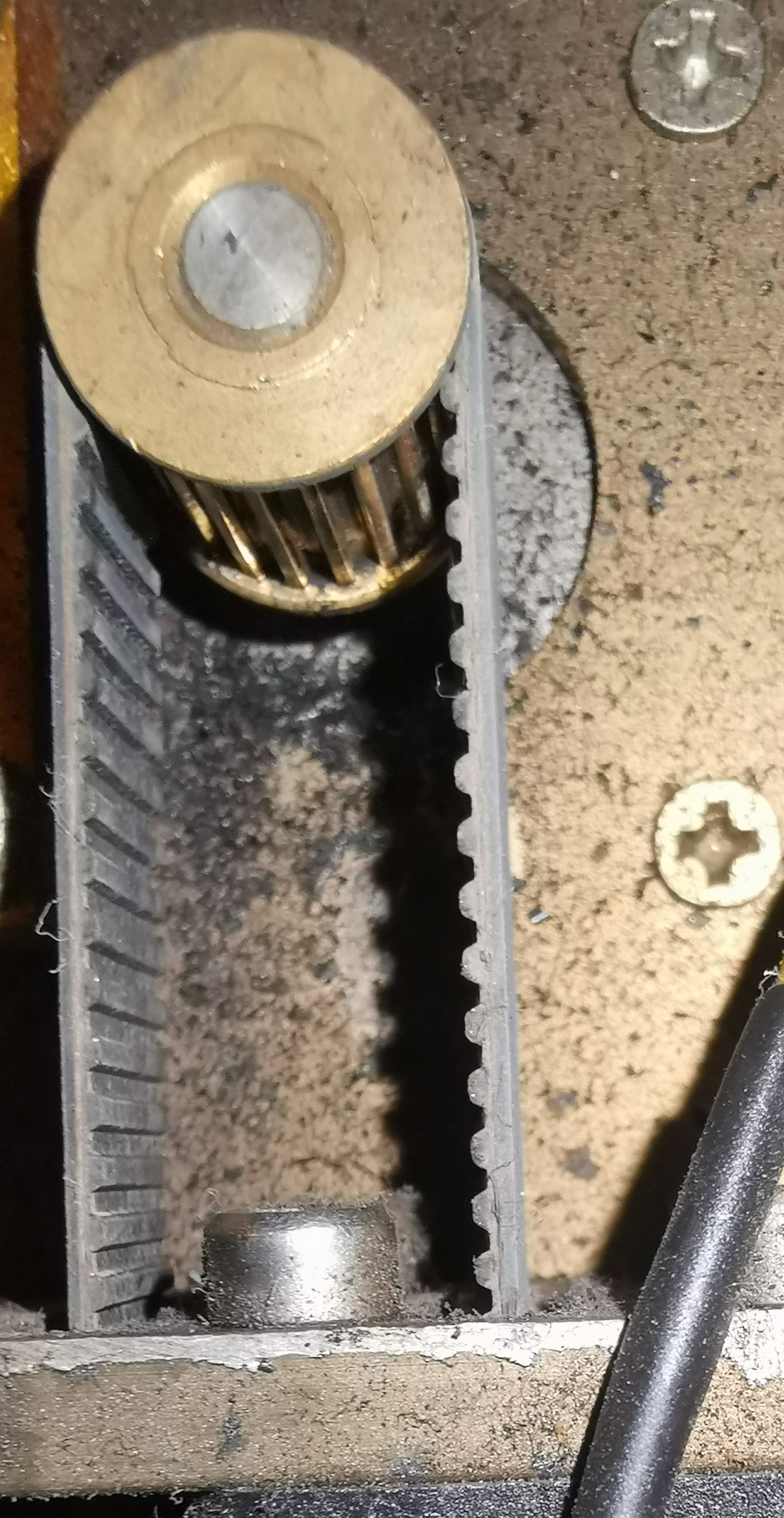
Update for not to let die this topic. I did check all the belts and I think X axis belt teeth seems worn-out, so I decided to order the X-belt to change it. Still waiting for it arrive this week. I also made a clean up to the machine because the axis pulley was very dirty, that´s why I think the X axis teeth were damaged. Once I change the belt, I´ll keep making tests.
That’s a new one on me, but definitely a place where the axis can lose some motion. The belts and pulleys depend on exactly matching shapes for precise motion: those flat-topped teeth aren’t helping!
A new belt should get you a lot closer to the goal.
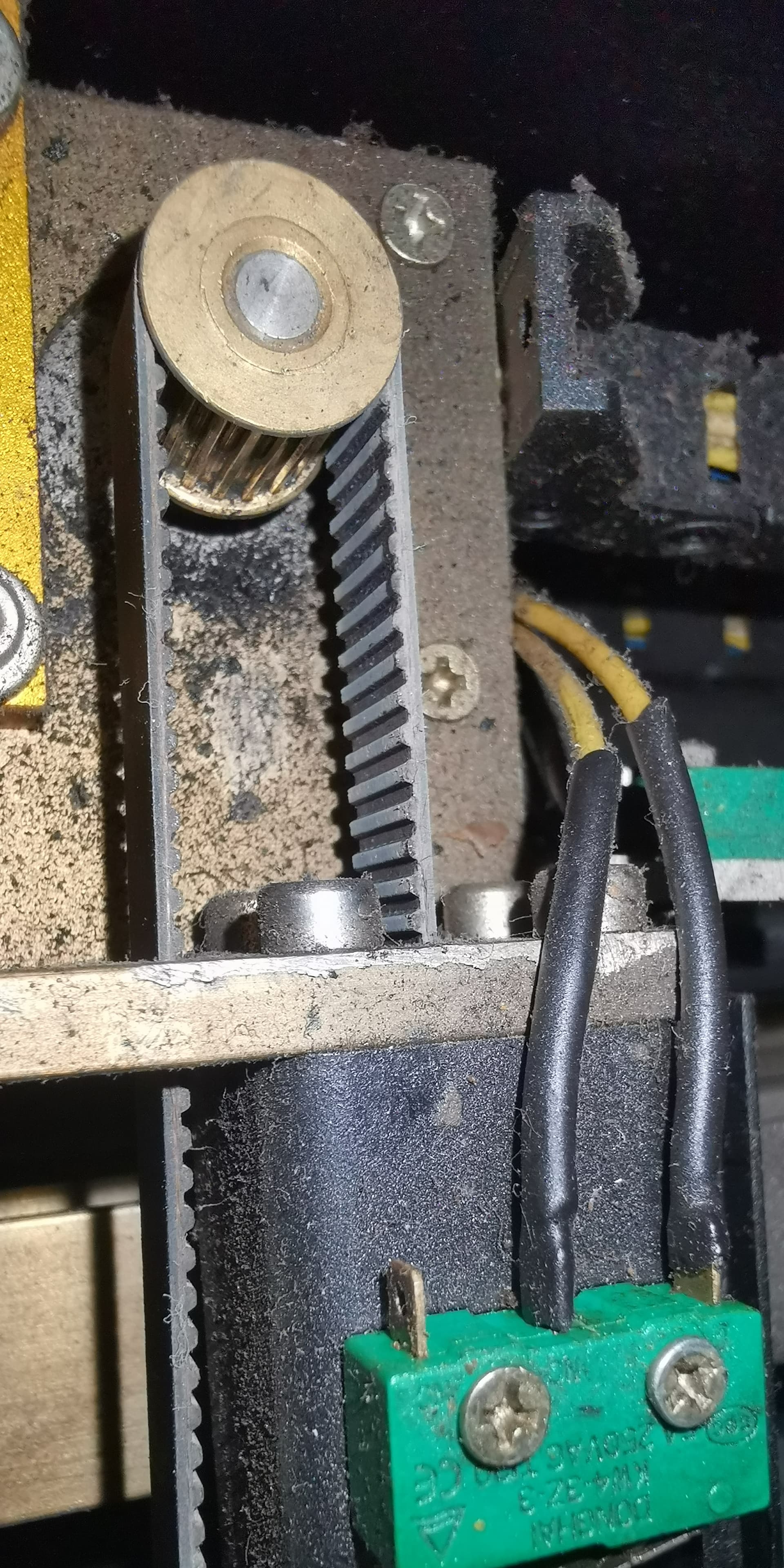
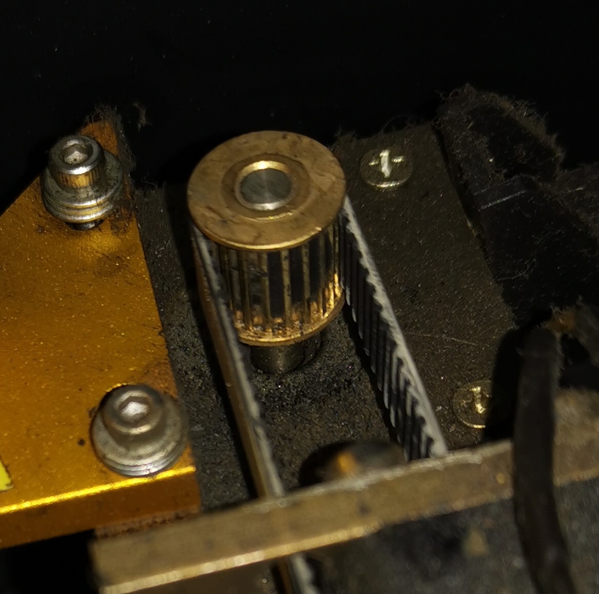
That damage is pretty gnarly. I’d suggest doing some proper investigation to figure out root cause or you may be back in this same spot. The only time I’ve ever seen that much belt dust was when there was a belt that was not properly threaded through an elaborate belt path and was rubbing directly against a non-bearing surface.
I’d suggest double checking that the belt is indeed threaded properly. Some other possibilities include:
belt path is not linear. In other words, the path of the belt is not on a plane and has to bend slightly at some point.
belt is overtensioned
belt does not actually fit hardware
belt is of poor quality
this is just wear and tear from thousands of hours
The axis belt is the one it came with the laser machine originally, so I want to think it´s not a bad quality. About the tension, well, in this case I´ll have to ask the correct way to change and tension the axis belt.
Thanks for the advice, I´ll check all around to make sure everything is working properly and I hope the root cause be just the dirt on the pulley. I clean up some parts of the laser machine, but I missed some other parts like pulleys or rails. I must to pay attention on those in the future.
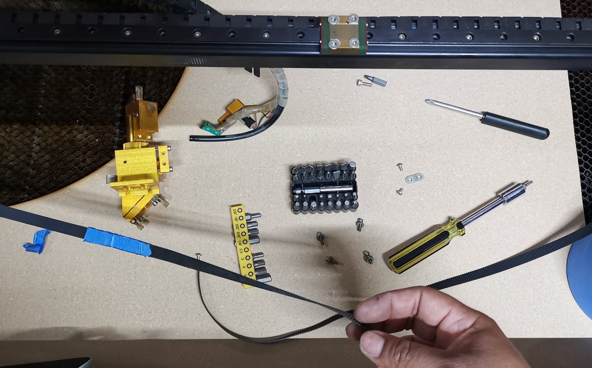
Finally I got the axis band after a long time.
Due to I have some pendings, I’ll replace it on Thursday. This comment is to not let die this topic. I hope replacement be the final solution.
X axis belt replacement was done. I performed some tests like mirror alignment and X axis movement performance. Everything looks good until I made a cutting test.
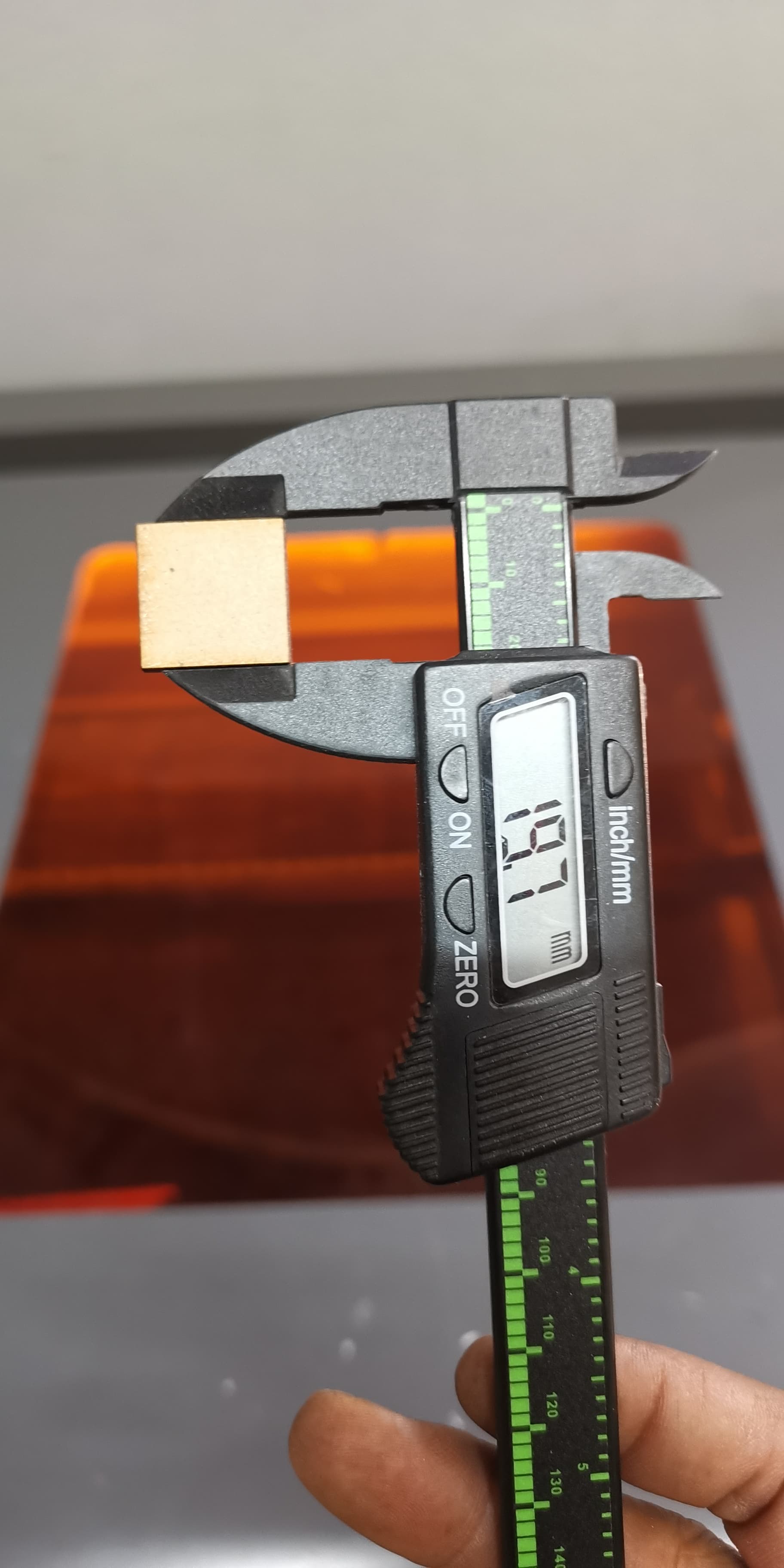
I drew a square in Lightburn size 20x20mm,the result was a measure of 19.7x19.7mm using a caliper. I compensate it adding 0.3mm and the result was 20x20mm, so there’s a difference of 0.3mm in height and width.
I’m pretty sure that’s not correct and I don’t know how to fix it. Can anyone put me in the right direction to solve this issue?
Well, I fixed the issue of measure difference calibrating the axis (thanks to a video of the Louisiana hobby guy).
The main issue still remain after all procedures mentioned before. It seems there isn’t any more to do here, so unless anyone have experiment the same issue and solved, my theory is that my Chuck Rotary Tool won’t work with Ruida controller or vice versa.
I came to that conclusion because the first time (almost 2 years ago) when I tried to use the chuck rotary tool, it didn’t work (it didn’t spin when pressing the Y axis arrow buttons) and no one could tell me why, not even the vendor. Then, after some months later, I found a video where it explained that the rotary tool won’t work until update the RUIDA driver controller.
After update, I finally could get the motion of the spining in the rotary works, but then the issue for I opened this topic appear for any tumbler I want to engrave.
This has been a headache for months, so I’ll let it go. No solution for this.
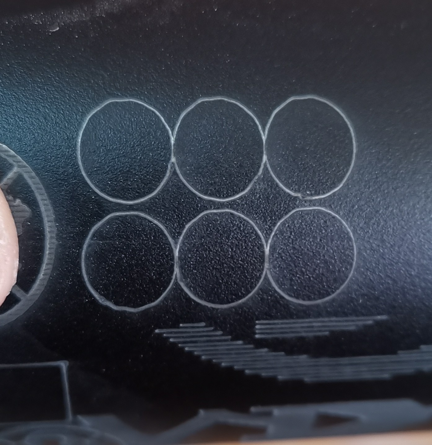
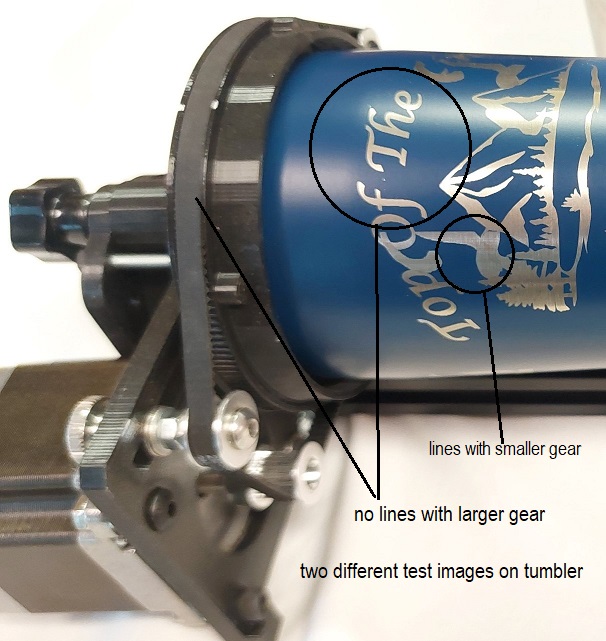
There is a solution, and when I was having the EXACT same problem it turned out to be the gear ratio between the GT2 pully on the stepper motor and the gear that the tumbler was attached to. When I went to a larger gear ratio the lines went away. In my case it resulted in more mm per rotation which resulted in smaller steps. I’m assuming the gear ratio on your rotary can’t be changed, but you might get there by tweaking the settings. The picture shows (somewhat hard to see in this pic) what happened when I went from a 12mm/50mm gear setup to a 12mm/100mm one. The lines disappeared.
I´m not an expert at all, it is obvious, but it supposed to be a “formula” to calculate the steps per rotation. If this were the case, it will be very difficult to calculate steps per rotation for each different tumblers. Anyway, I have nothing to lose making some tests. I hope this be the final solution.