Thank you for your replies
ednisley
If I’m following the sequence of events correctly, you have now eliminated all the mechanical backlash: congratulations!
Unfortunately, this is only the case on larger objects. On smaller objects there is still some noticeable backlash!
ednisley
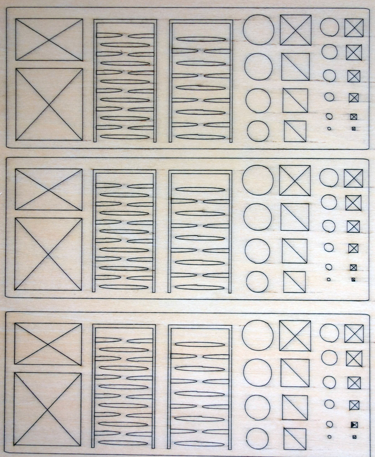
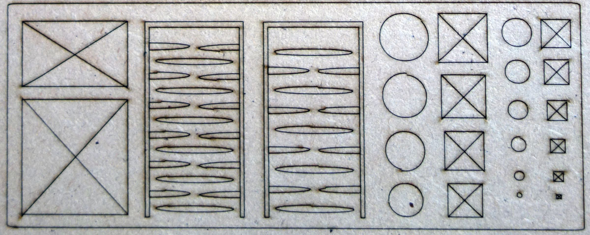
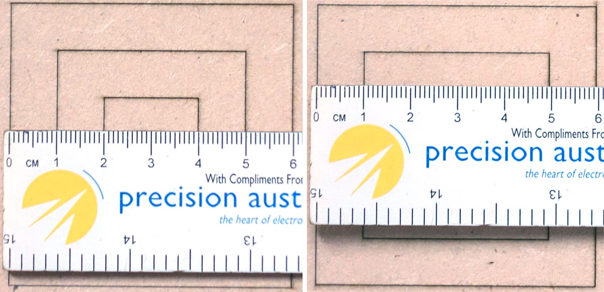
That’s small enough to come from the non-square shape of the diode laser beam: it’s wider along one axis than the other. Not by much, mind you, but enough to make a difference for fussy folks such as you and I. The path around the circles and the rectangles looks darker on the left / right sides and lighter on the top / bottom sides, because the beam is wider along the X axis than the Y axis.
That is correct, but the beam size is only 0.06 x 0.08mm in size, so I can’t see that an extra 0.02mm create a 0.5mm difference.
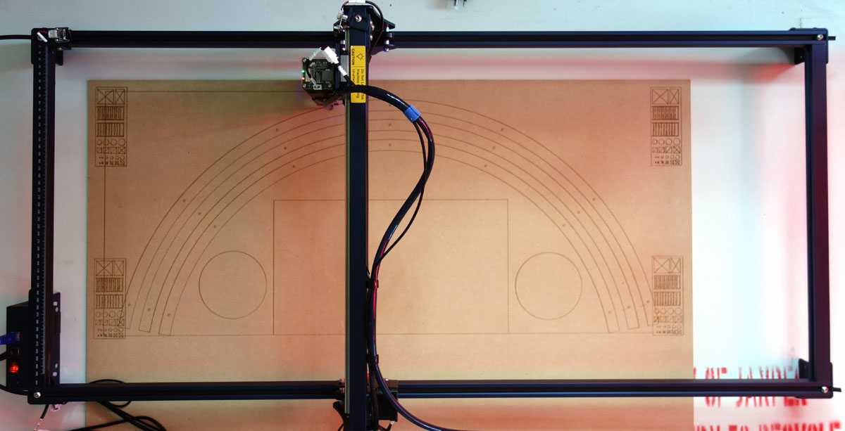
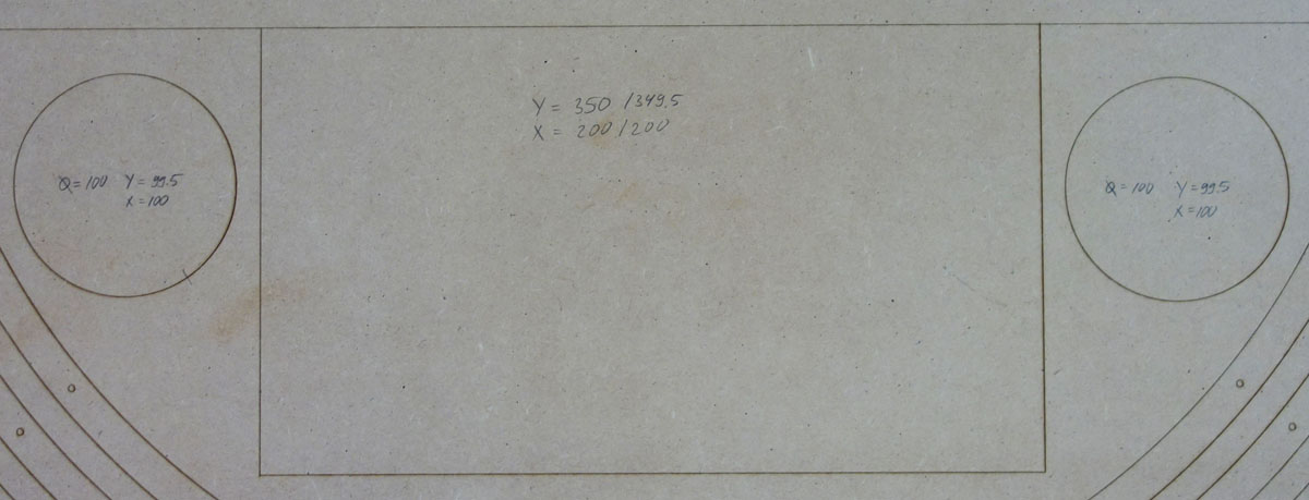
The Axis scale check is a linear issue = the longer the distance, the more the difference. But in my case every dimension in the Y axis is 0.5mm shorter - a 5mm rectangle is 4.5mm in the Y axis and a 500mm rectangle is 499.5mm! Indeed, no big deal on large items, but on small items it is a different story.
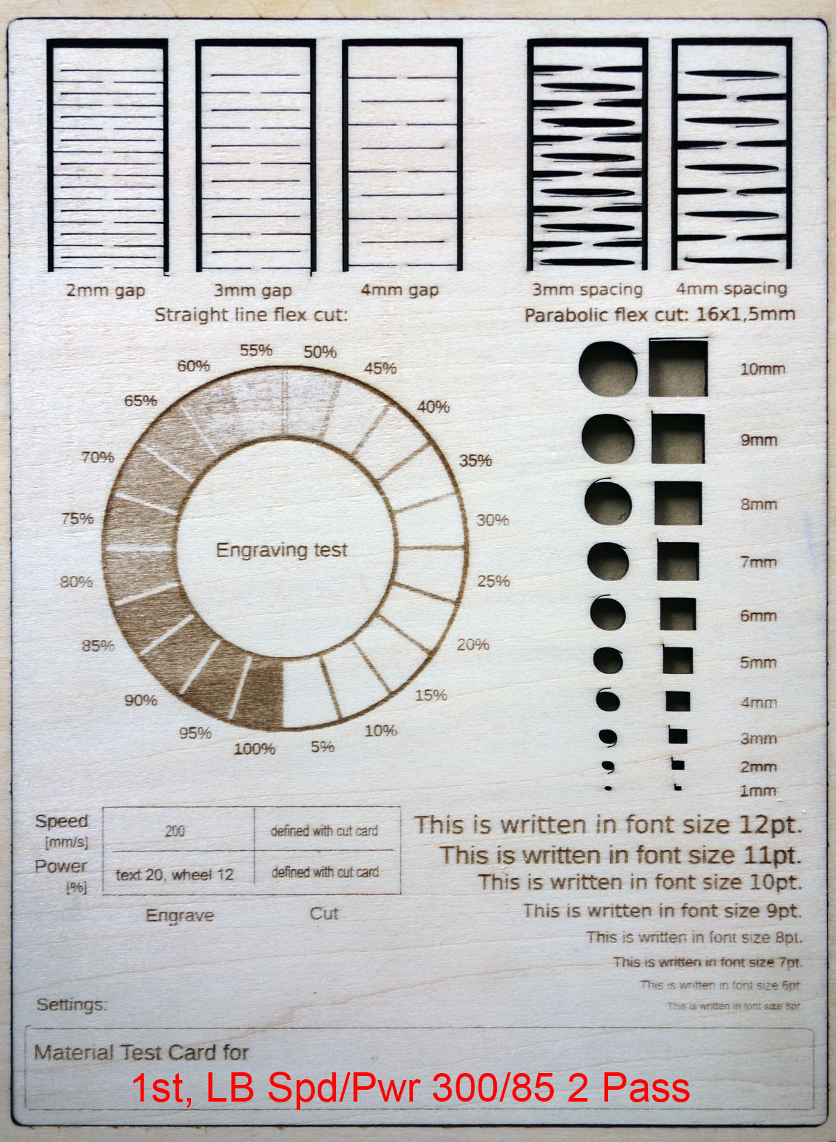
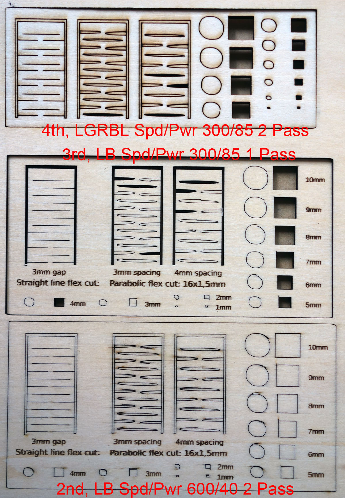
X axis on the left, Y axis on the right
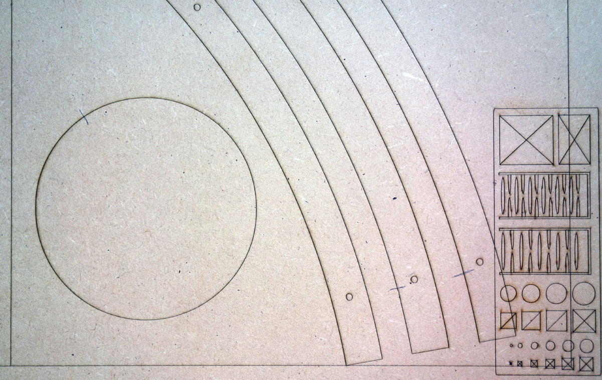
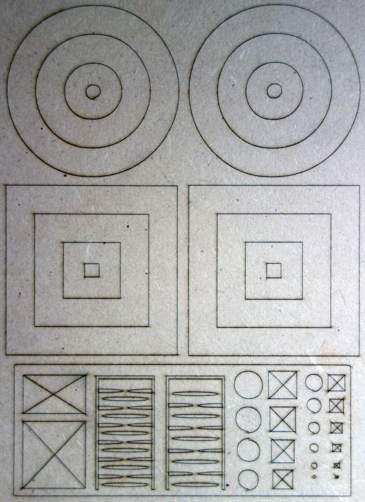
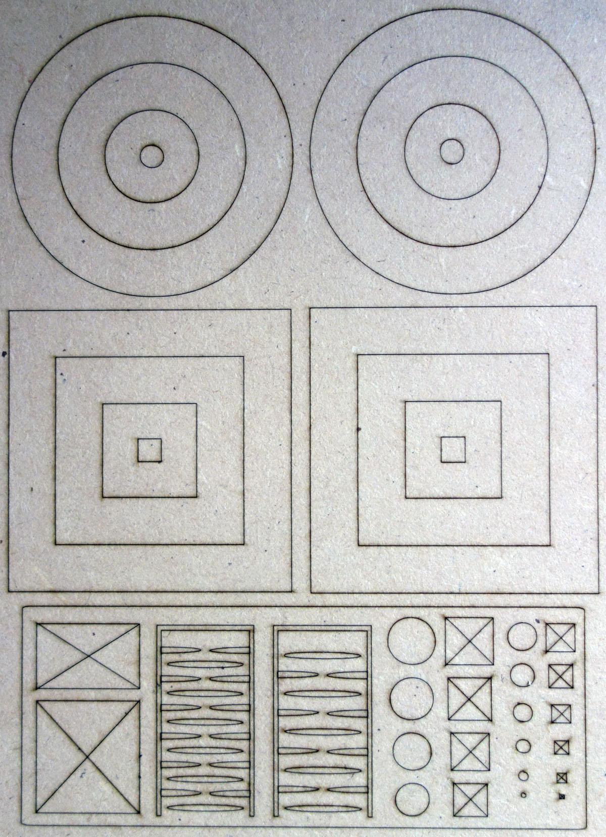
When I increase the belt and wheel tension, the backlash in the ovals disappeared, but it is more pronounced in the circles instead. But the Y axis dimension is still 0.5mm shorter
The same is the case if I make them looser. The rectangles and circles on the righthand side are 0.5mm longer in the Y dimension to compensate the error and it does work.
I could improve things by playing around with the belt and wheel tensions and using hide backlash option in LightBurn.
Unfortunatly this doesn’t correct the 0.5mm error. But I did come across some forum posts of people having similar issues when using the Y axis extension like I do. So I guess you are right in saying that it is the physical limits of the machine! And the fix is to add 0.5mm to the Y axis dimension in the design. Regards, Peter