I’ve tried all the other fixes on this forum for this issue and they have not worked. I have never run a rotary table. I’ve recently installed limit switches on my laser and since have not been able to engrave circles. I’m running NEJE 30W Laser and a MKS DLC32 Laser Controller.
Also, I don’t know if this is useful but when i restart a program after it goes to it’s finish point it doesn’t start in the same spot. When I rehome and try to start something in the same exact spot it does not work either.
Sorry for the incomplete info never posted before. Yes the problem began after installing the limit switches. I attached a photo of the circles. The are just open circles that are oval shaped as if I had the rotary on but i don’t
Judging by the values, I would say that the board is at factory values and should be correctly configured.
Maybe if you calibrate the axis you can fix the problem.
That looks like a pretty severe mechanical slippage. What all did you touch (loosen/remove/push aside) during your switch installation? Belt tension, pulley/pinion/coupler grub screws are most common. If the mainframe or gantry came apart, also check for square/perp/parallel all around.
I’m very confident it’s not mechanical slippage due to belts or pulleys and all three motors are brand new. Before I came here I checked EVERYTHING from head to toe on the machine and made sure everything was tight and watched as it ran to see if there was any slippage. It’s not slipping seems like it’s intentionally running that way.
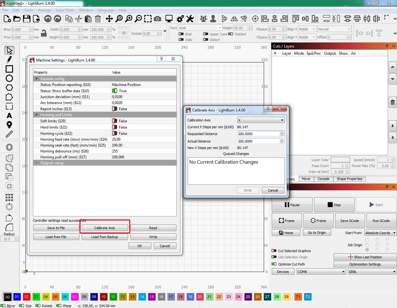
It is a brand new machine and I’ve never calibrated the axis but I’m not sure how to properly do it. Mine just says no changes to calibrate and I don’t know what to change.
Actually, this is a mechanical issue, I’m 95% sure. You can also see that start and end points do not match. That’s mechanical.
You can calibrate axis, but this is only required to do the last 5% of accuracy. Your circles are so much off, it’s nothing to do with settings.
Slippage is nothing you really see visually. Furthermore, the opposite can also happen, wheels and belts are too tight and the laser is loosing steps. Also check all the grub screws at the motors and the movement mechanics. Did you check the wheels? Those are much more important than the belts. Here is a list (and it’s long) of all things you might check: Guide to mechanical adjustments and maintenance
Oh yeah. Rollers. I always forget those. I’m still setting up my first roller machine. I prefer linear bearings, but I got a good deal and for some reason nobody wants to put linear bearings on a machine with a 5W laser. “Better precision” laser but a fiddly 2020 roller drivetrain with no belt tensioners. Sigh. Lol.
I was absolutely wrong. It was a grub screw on the tension pulley to one of the axis motors I changed. Thank you guys. I’m working through the list of mechanical adjustments and maintenance still. I’m getting perfect circles now. My next question is how do I calibrate my axis motors?
Most likely not required. In 99% you don’t need to adjust them. But the easiest way is to laser a square like 100x100mm, measure the result and then calculate the new steps/mm (or let the LB assistant do that, screenshot is a few posts above).
Make sure to measure from center to center of those lines, do not measure the outer dimension of the square.
Calibration can change the absolute size and aspect ratio of shapes, but won’t fix geometric anomalies like wiggly lines, disconnected ends, inconsistent curves, drifting, etc.
Easiest way to calibrate is to lightly engrave (not cut!) Something fairly stiff and flat (chipboard, MDF, etc) using a square as large as the machine will allow. A nice round number is fine. Say 400x400. The bigger, the better. Using the most accurate measuring instrument you have, measure from center to center of lines on opposite sides. Jot down the programmed dimensions and the physical measurements then use the calibration widget in Lightburn to calculate and apply the correction.
Cutting will produce a smaller dimension due to kerf. This is where kerf offset adjustment comes in. Once the axis calibration is complete, you can do kerf. This is very much material dependant (it will be different for every material/thickness) and is stored in the cut settings. Axis calibration is global. Once and done.