As the saying goes, “A picture is worth a thousand words”. Here are several thousands words for your enjoyment! ![]()
I built my own laser using a few parts from a small Two Trees laser unit I purchased a few years ago. I wanted to be able to engrave larger items such as kitchen cutting boards and whiskey barrel lids. I ordered a box of 100cm 20x20 vslot rail and had a blast!
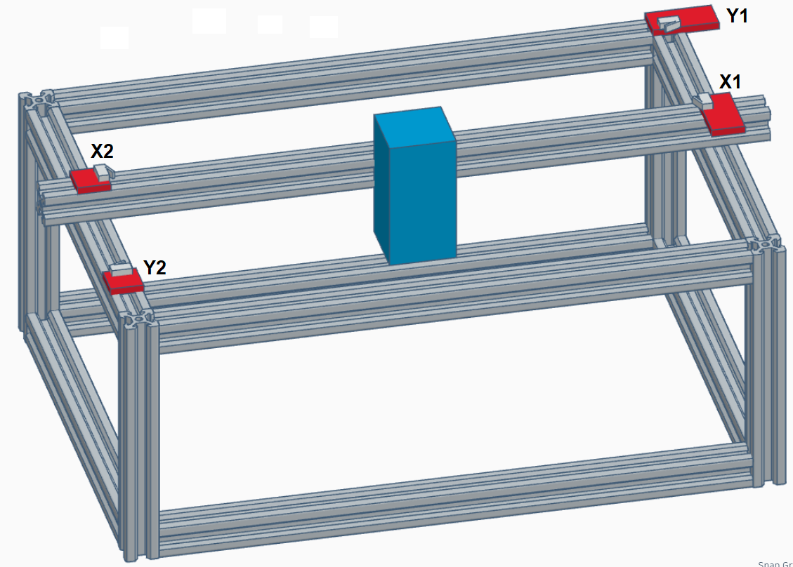
Here’s a basic graphic of my unit:
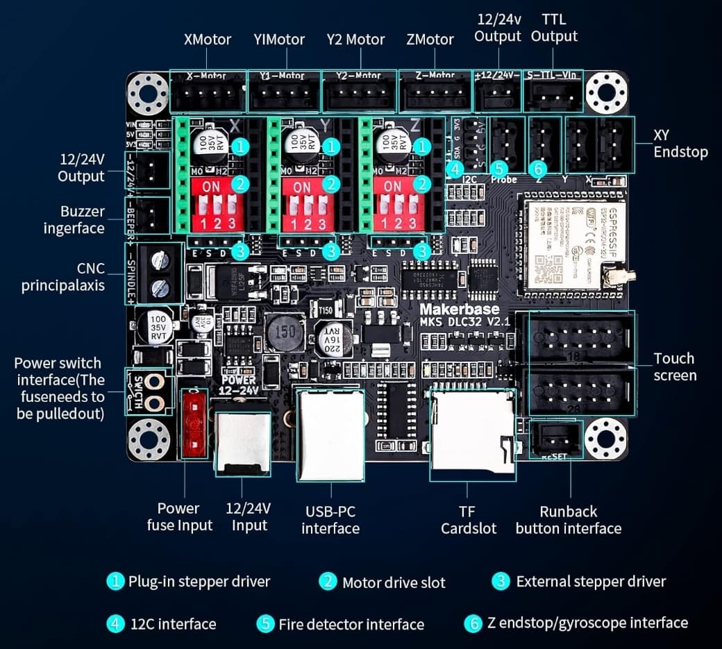
I’m using the Makerbase DLC32 V2.1 controller:
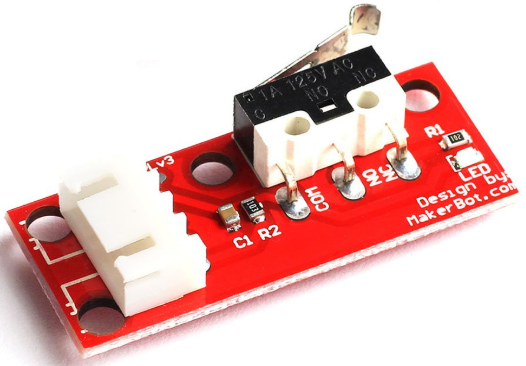
X1 and Y1 are Makerbot Endstop Limit Switches. These are connected to the X and Y endstop connectors on the controller with straight wires:
X2 and Y2 are microswitches I removed from another brand endstop switch and mounted them with 3D printed mounts I made:
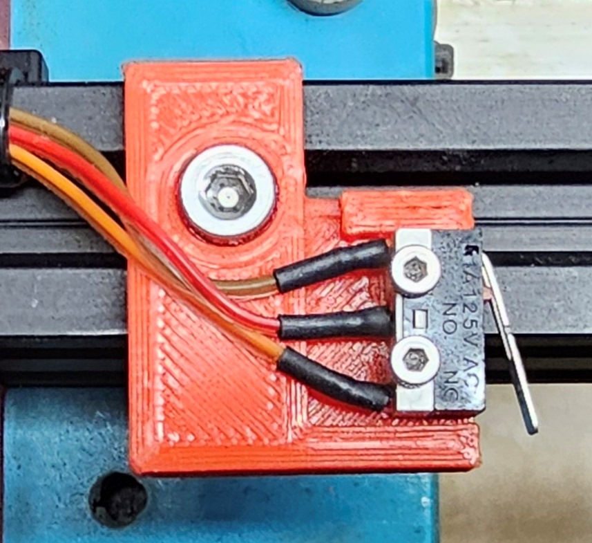
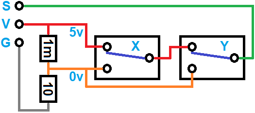
X2 and Y2 are connected to the Z endstop connector on the controller using this circuit I built. It incorporates a voltage divider to provide 0 volts:
When I started on this project, I connected one of the Makerbot endstop switches to my variable power supply and observed the output of the “S” pin when the microswitch was pressed. I was seeing 5 volts not pressed and 0 volts when pressed. I assumed the 0 volts was ground, but that turned out not to be the case. When I created a simple circuit with a microswitch so that I switched between 5 volts and ground, the controller reset when the switch was pressed, so that told me that the Makerbot endstop switch was not switching between 5 volts and ground.
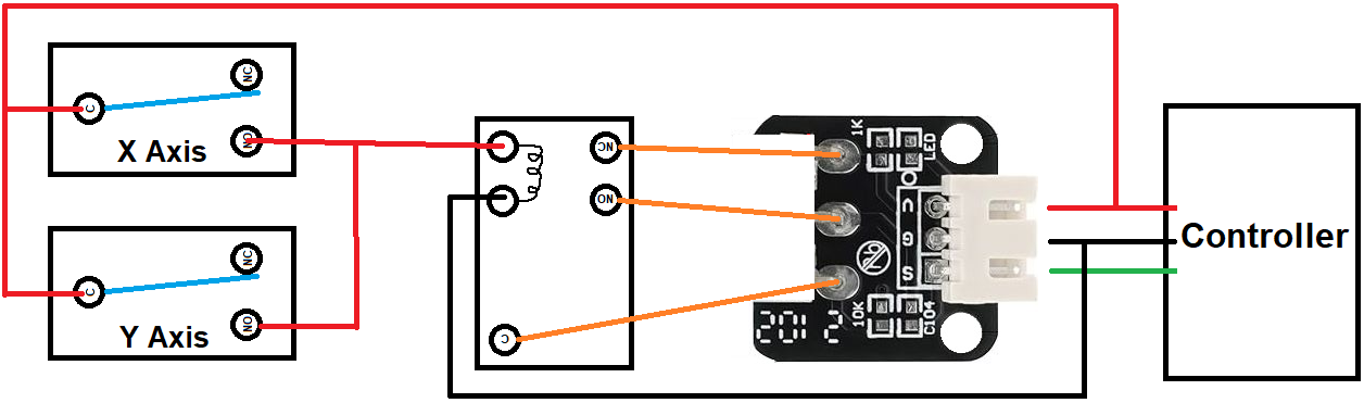
Using parts I had on hand and wanting to move past the project as quickly as possible, I used a 5 volt relay, removed the microswitch from a an endstop switch, and connected the relay to perform the function of the microswitch:
This worked perfectly, but I kept thinking that there was a more simple solution that wouldn’t require a mechanical relay. Since it was working and I have several other projects to work on, I decided to leave it as is. But, as usual, my subconscious kept working on it and a solution popped into my head while I wasn’t even thinking about it. This happens a lot to me!
A simple voltage divider using a 1 meg ohm and a 10 ohm resistor provides the “0 volt” input the controller is happy with. It actually measured 3 millivolts on the DVM, but that appears to be close enough. When X2 or Y2 is pressed, the head stops moving instantly, and a “Hard Limit” message pops up on the DLC32 controller screen.
I realize that there are many different controllers out there, and each has its own method of interpreting limit switches. Switching between 5 volts and ground make work on some, but not with the Makerbase DLC32 controller.
I hope this post helps others and saves time and prevents frying controller boards!