Circuit for two additional limit switches

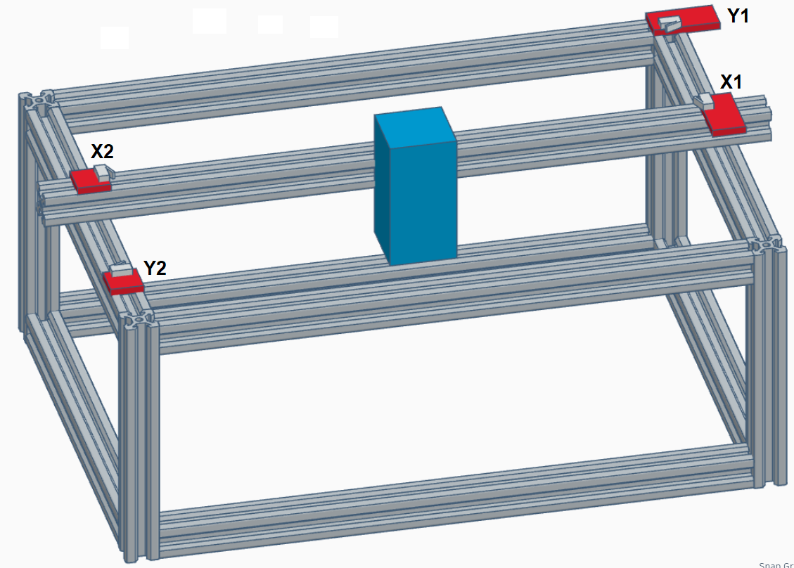
My laser is equipped with limit switches on the X & Y axis for homing the laser to the back right corner. Every once in a great while, I manually move the head to check something and forget to home the head, & as a result, the head crashes into the front or the left, grinding the steppers.

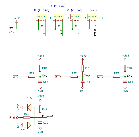
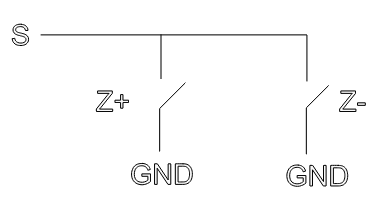
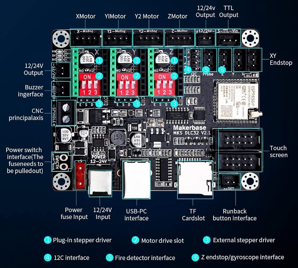
I’m using the Makerbase DLC32 v2.1 controller, & came up with my own design for adding two additional limit switches connected to the unused Z limit switch input of the DLC32. Due to how limit switches work, two of them can’t be connected in series or parallel.

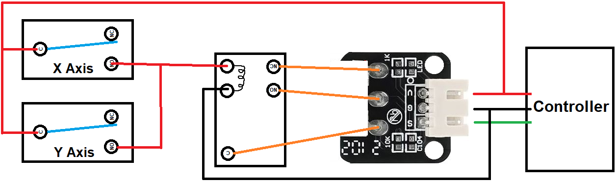
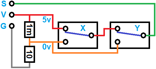
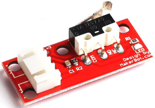
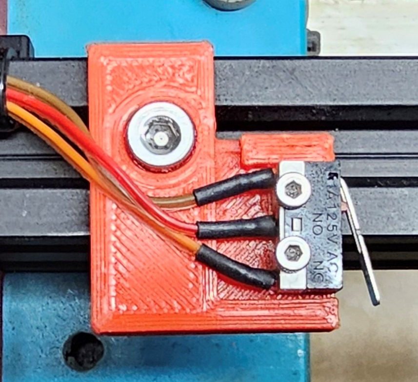
What I did was mount two micro switches in parallel that control a 5 volt SPDT relay. I removed the microswitch from a limit switch circuit board I already had, and connected the Common, NO, and NC of the relay to the corresponding microswitch points on the limit switch circuit board.

Since these limit switches will rarely be hit, I decided to use the “normally open” contacts of the microswitches so that the relay wouldn’t be “energized” for many hours on end, waiting to be useful. I figure it would extend the life of the relay by going this route. When either microswitch is hit, it sends 5 volts to the relay which in turns provides the proper input to the limit switch circuit board.

Can anyone offer a more “elegant” solution that might eliminate the relay and cannibalized limit switch? I did some experimenting with “pull up” and “pull down” resistors but couldn’t come up with a circuit that would work.

Thanks!

Not sure if I follow you, I have a DLC32 V2.1 also. Not really sure why you are moving the manually. The machine will lose it’s location if you manually move the head. Probably why it’s hitting it’s rails.

This is a standard wired or input configuration, so your statement isn’t true.

The inputs of the limit/home switches only need to be pulled low, so, yes the switches can be paralleled or series depending on a pull down (parallel) or pull up (series) configuration.

This is the home, probe input section of the dlc32.

:smiley_cat:

2 Likes

I’m referring to the limit switch circuit boards, not just simple microswitches.

I need help with building the actual circuit. Connecting the signal pin on the DLC32 Z axis limit switch input to ground reboots the controller

That’s not correct. You can always wire them in parallel. And that’s the best way to do it. If you like to have two switches for one axis, just wire two of them in parallel. The firmware can’t distinguish which one was pressed, but that’s not required since the firmware can’t handle this anyway. It only needs to stop.

Wiring to the z-limit switches does also not make sense because the laser does not stop on these, once hit (in standard configuration).

You are thinking way too complicated for a simple setup :slight_smile:

Then cut the VCC line of the switches. Here is some background information:

Although the switches can be connected in parallel (for NO contacts) or in series (for NC contacts), that may not be possible if they’re on PCBs with additional circuitry.

I ran into that problem using Makerbot-style switch PCBs on my embiggened 3018:

The NC terminals connect the power supply to the COM terminal, so wiring them in parallel puts a dead short across the power supply when the NO contacts in either switch close. I amputated the offending NC terminal at the switch and continued the mission:

It seems like you’ve just encountered that problem, too. :frowning:

1 Like

I was hoping for a more simplified circuit, but there doesn’t appear to be. If I could find a schematic and a parts list, I could easily build it. What I created using to microswitches, a relay, and a limit switch circuit board connected to the Z limit switch input works perfectly. If either of the microswitches is pressed, the head instantly stops moving.

I appreciate all of the input! I need to move onto other projects, so I’m going to stick with what I have in place. I just added a small CNC machine (Genmitsu 3018 PROVer V2) to my hobby shop and I want to spend some serious time getting into that. On the CNC machine, each of the three axis have dual limit switches. One of the limit switches on each axis has a 6 wire connector. They have apparently designed a circuit that incorporates two switches for each limit switch input to the controller.

Thanks!

1 Like

This is because the CNC has screw drives. The torque is much higher and something can break rather than stall out the stepper motor.

You did not mention Zaxis in this statement. We all eventually thought you were using the Zaxis switches to stop X & Y. We cannot see what you see in your head. Confusing answers are based on confusing information.

Unless you have limit switch modules like @ednisley said you might, @jkwilborn and @misken are exactly right. Both options are covered here.

This is because grounding the switch is shorting an input not configured for that. Luck you did not smoke the controller board input. @ednisley gave you a schematic that should help.

Statement:

Reply:

Thanks for the info. Sorry for the confusion. I’m going to stick with what I have for now as it’s working fine. The weather’s getting nice & will see mostly outdoors. Lots of camping, sailing, kayaking, cycling, hiking to do!

If it ain’t broke, don’t fix it. :joy:

I raised 2 boys at King’s Island. Better than a 13 hour drive to Orlando.

Actually, I did specify the Z axis in the original post.

Don’t get offended. In the first paragraph you described adding X&Y switches. In the second you were wiring to the Z inputs. It was easy to see that X+Y=Z. As they said in the Independence Day movie, “What we have here is a failure to communicate.” :joy:

Glad you found a solution to the problem, and thanks for sharing. Others will benefit.

Next time I’ll include video & pictures…:winking_face_with_tongue:

1 Like

As what usually happens for me, if I can’t figure something out, all I have to do is stop thinking about it and let my subconscious work on it, and the answer will pop into my head when I’m not thinking about. This has happened thousands of times during my life. It’s wild how our brains function!

Once I understood how the limit switch circuit boards worked and what the controller was looking for, the solution was rather simple. The limit switch “signal” input on the controller is expecting for either 5 volts or 0 volts, so a voltage divider was all that was needed to provide the 0 volts via a 1 meg ohm and a 10 ohm resistor. It’s not precisely 0 volts but it’s low enough to give the controller what it needs. My meter showed 3 millivolts.

The two microswitches are wired in series as shown in the diagram. When neither switch is pressed, 5 volts flows to the Z axis limit switch signal input on the controller. When either of the switches is pressed, 0 volts flows and a “Hard limit” error pops up on the controller LCD screen, and the head instantly stops moving.

I knew that a more simplistic solution was rattling around my head somewhere!

This is a positive logic setup. These boards usually default to a LOW being active. All of these, that I’ve dealt with, have a pullup resistor ensuring S is pulled high normally. This is a wired OR.

So all you really need to do is to wire them to ground using a no (normally open) switch. Either one is activated it goes to ground, so S is grounded or active.


Your circuit is a wired AND. It should work either way. If you want to use your circuit, you need to ensure you configure the controller correctly.

Make sense?

:smiley_cat:

Grounding the “S” pin resets the controller. It appears to be looking for “0 volts” as opposed to “ground”. I tested it several times with the new circuit & it works perfectly. I’m happy to have eliminated the mechanical relay from the first design.

Also, the two micro switches are mounted on the left side of the X axis and the front of the Y axis, on the opposite ends from the limit switches used for homing in the back right corner. The two new switches are there to prevent the head from crashing into the front or left rails in case I forget to home the head after moving it manually. A rare event, but it does happen.

On these, what’s the difference?


The S pin, for a limit/home switch, shouldn’t reset it, unless you exceed the Z height after it boots. These become limit switches after the machine boots.

This is very simple. I have at least three machines with home/limit switches. I sure didn’t go through this much trouble.

I’m wondering if we’re on the same path…?

:smiley_cat:

As the saying goes, “A picture is worth a thousand words”. Here are several thousands words for your enjoyment! :winking_face_with_tongue:

I built my own laser using a few parts from a small Two Trees laser unit I purchased a few years ago. I wanted to be able to engrave larger items such as kitchen cutting boards and whiskey barrel lids. I ordered a box of 100cm 20x20 vslot rail and had a blast!

Here’s a basic graphic of my unit:

I’m using the Makerbase DLC32 V2.1 controller:

X1 and Y1 are Makerbot Endstop Limit Switches. These are connected to the X and Y endstop connectors on the controller with straight wires:

X2 and Y2 are microswitches I removed from another brand endstop switch and mounted them with 3D printed mounts I made:

X2 and Y2 are connected to the Z endstop connector on the controller using this circuit I built. It incorporates a voltage divider to provide 0 volts:

When I started on this project, I connected one of the Makerbot endstop switches to my variable power supply and observed the output of the “S” pin when the microswitch was pressed. I was seeing 5 volts not pressed and 0 volts when pressed. I assumed the 0 volts was ground, but that turned out not to be the case. When I created a simple circuit with a microswitch so that I switched between 5 volts and ground, the controller reset when the switch was pressed, so that told me that the Makerbot endstop switch was not switching between 5 volts and ground.

Using parts I had on hand and wanting to move past the project as quickly as possible, I used a 5 volt relay, removed the microswitch from a an endstop switch, and connected the relay to perform the function of the microswitch:

This worked perfectly, but I kept thinking that there was a more simple solution that wouldn’t require a mechanical relay. Since it was working and I have several other projects to work on, I decided to leave it as is. But, as usual, my subconscious kept working on it and a solution popped into my head while I wasn’t even thinking about it. This happens a lot to me!

A simple voltage divider using a 1 meg ohm and a 10 ohm resistor provides the “0 volt” input the controller is happy with. It actually measured 3 millivolts on the DVM, but that appears to be close enough. When X2 or Y2 is pressed, the head stops moving instantly, and a “Hard Limit” message pops up on the DLC32 controller screen.

I realize that there are many different controllers out there, and each has its own method of interpreting limit switches. Switching between 5 volts and ground make work on some, but not with the Makerbase DLC32 controller.

I hope this post helps others and saves time and prevents frying controller boards!

Not to butt in, but (see what I did there?) I fail to see how this will keep you from crashing into the rails. Hear me out. If you’re scanning at speed and you hit the limit switch inertia will keep the laser head moving and you will still hit the rail, although it won’t sit there and grind because the stepper motors are no longer engaged, or am I missing something here?

That being said, it probably will prevent a problem during a low speed framing operation, although that doesn’t take overscan into account.

The switches are mounted to stop it short of the rails. When a switch is hit, it really stops fast!

This is total :poop:

I have a DLC32 V2.1 and it does work as I and the documentation has stated. Not as you keep saying, erroneously.


You’re the one making this way too complicated. It’s a simple system in which the controller can be configure for NO or NC switches.

The ESP32 has the ability to pull an input up or down with internal resistors. There is no need to include, or have a use for external resistors.


I don’t know of a controller where these are fixed, as you state. Even the Ruida can be configured for different switches.

The machine only boots to one quadrant, even the software should keep it from going out of bounds.

Have fun

:smiley_cat: