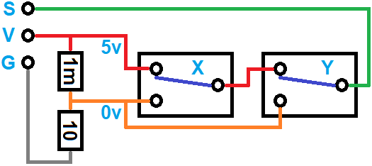
Well, I have to heavily apologize!!! I just finished cleaning up my workshop and came across the cord & connector I put together when I did my initial testing. I somehow managed to switch the VCC and S wires, so when I performed my tests, it was connecting VCC to G, not S to G, and that would explain why the controller rebooted. I did the same test on the Z and Y axis endstop controller inputs and it rebooted both times, so I decided that the controller wasn’t expecting to sense a fault when S to G where connected.
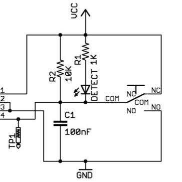
At that point, I examined the behavior of a Makerbot endstop switch circuit board on the bench using a variable DC power supply and a good quality digital multimeter. When the microswitch was not pressed, there was 5 volts on the S pin. When I pressed the microswitch, it showed .4 millivolts. This confirmed in my head that S should not be connected to ground, but should be registering a low voltage that it would be interpreted as “LOW” and create a fault condition. I performed the same test on another generic endstop limit switch compatible with the Creality 3D printers, and it showed .2 millivolts. This again reinforced my beliefs in how it should work.
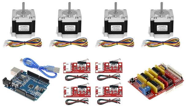
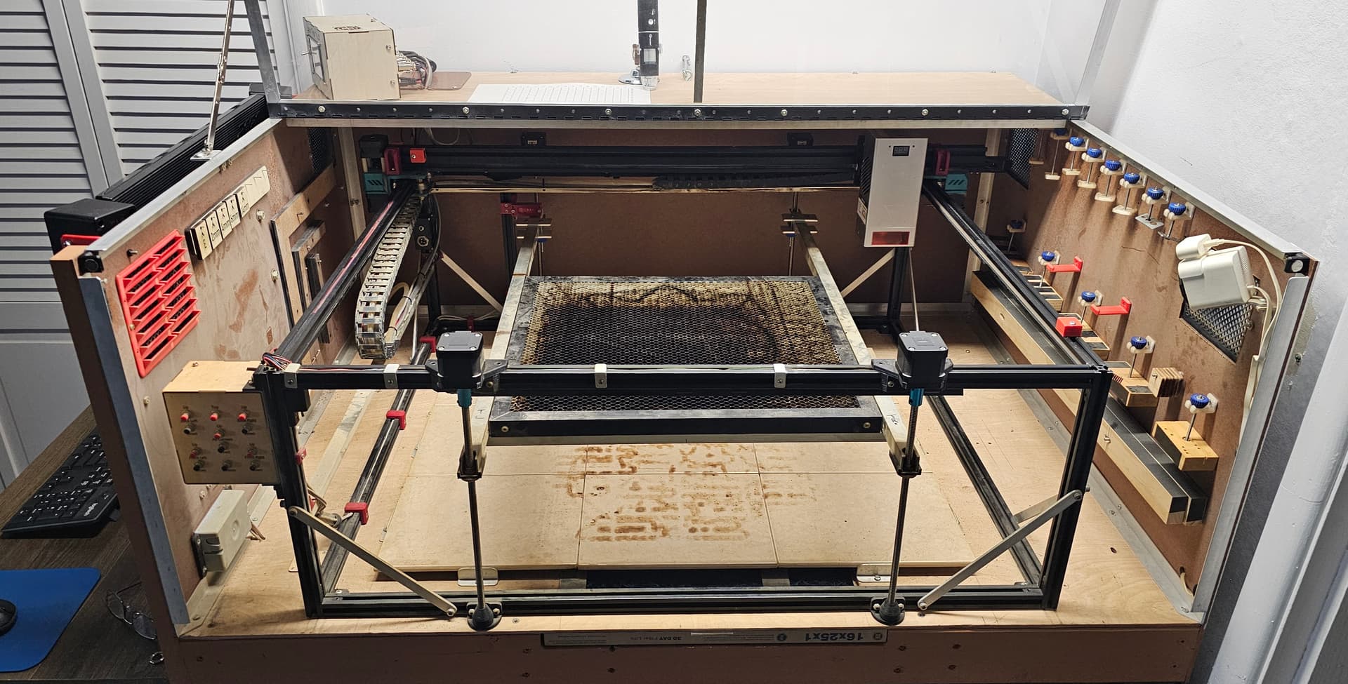
I’ve incorporated Arduino Uno, Nano, and Mega microcontrollers into several projects, including two on my laser setup. I added a motorized platform to make it really easy to adjust the height when needed. I used the Two Trees CNC controller kit.
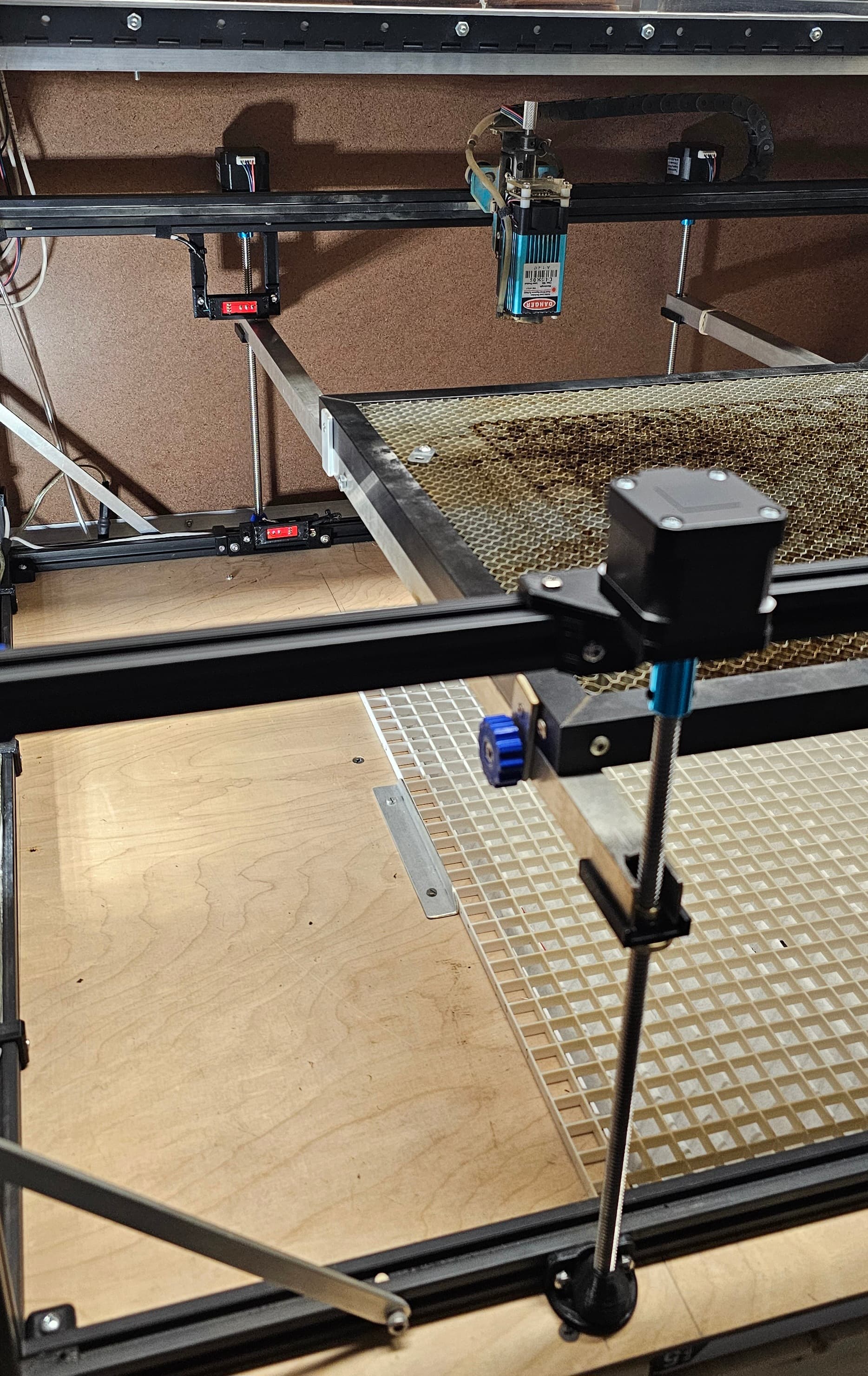
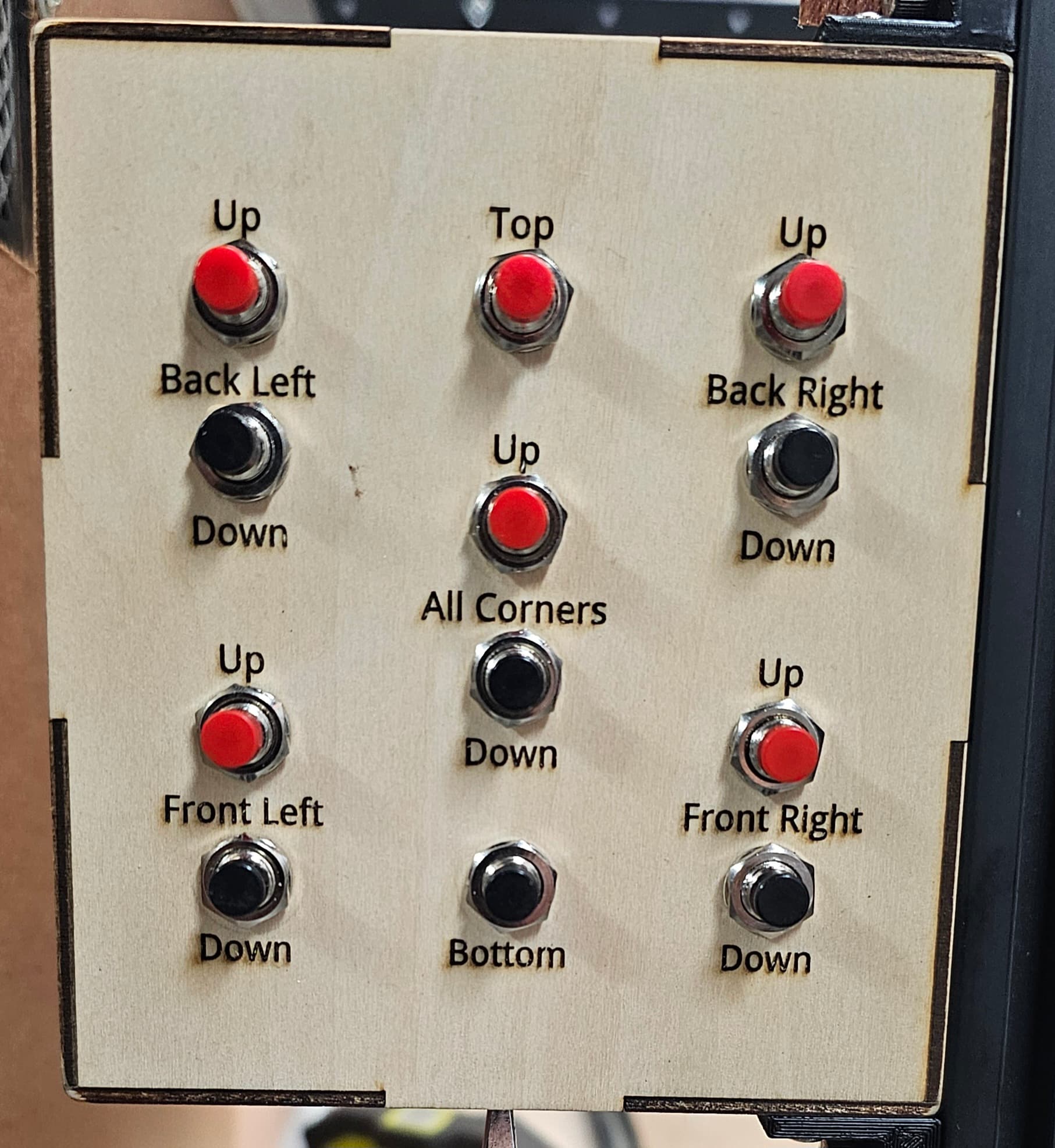
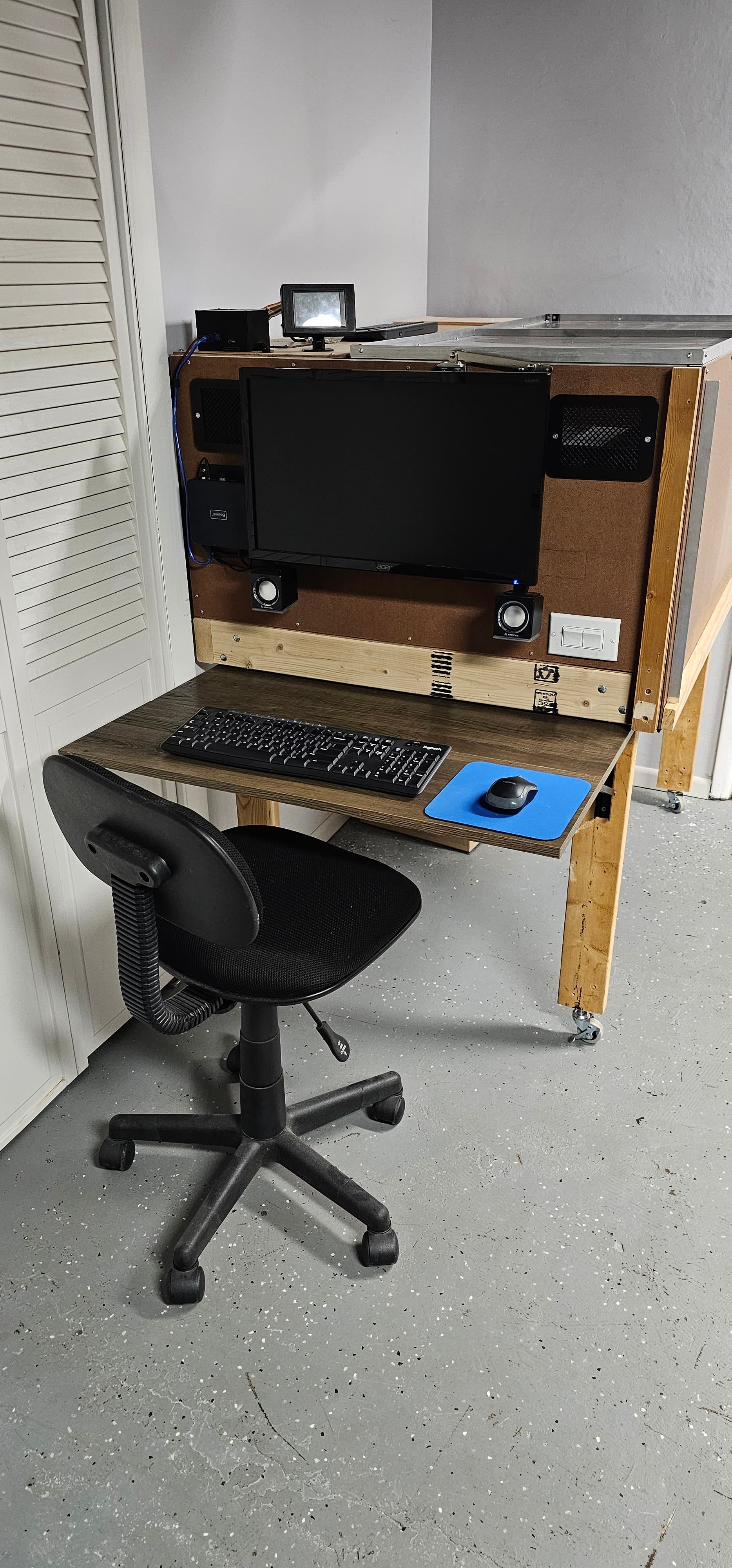
The two buttons in the center move the entire platform up and down. The other sets are used for the occasional calibration. The “Top” and “Bottom” buttons move the platform all the way up or down, using two limit switch circuit boards. I have a rotary tool for engraving the coated stainless steel cups, and also engrave a variety of objects of varying thickness, so being able to quickly adjust the platform height was been extremely nice. The laser head in the photo is my old 5.5 watt Two Trees head I started with. The new K60 has been sooooooo nice!
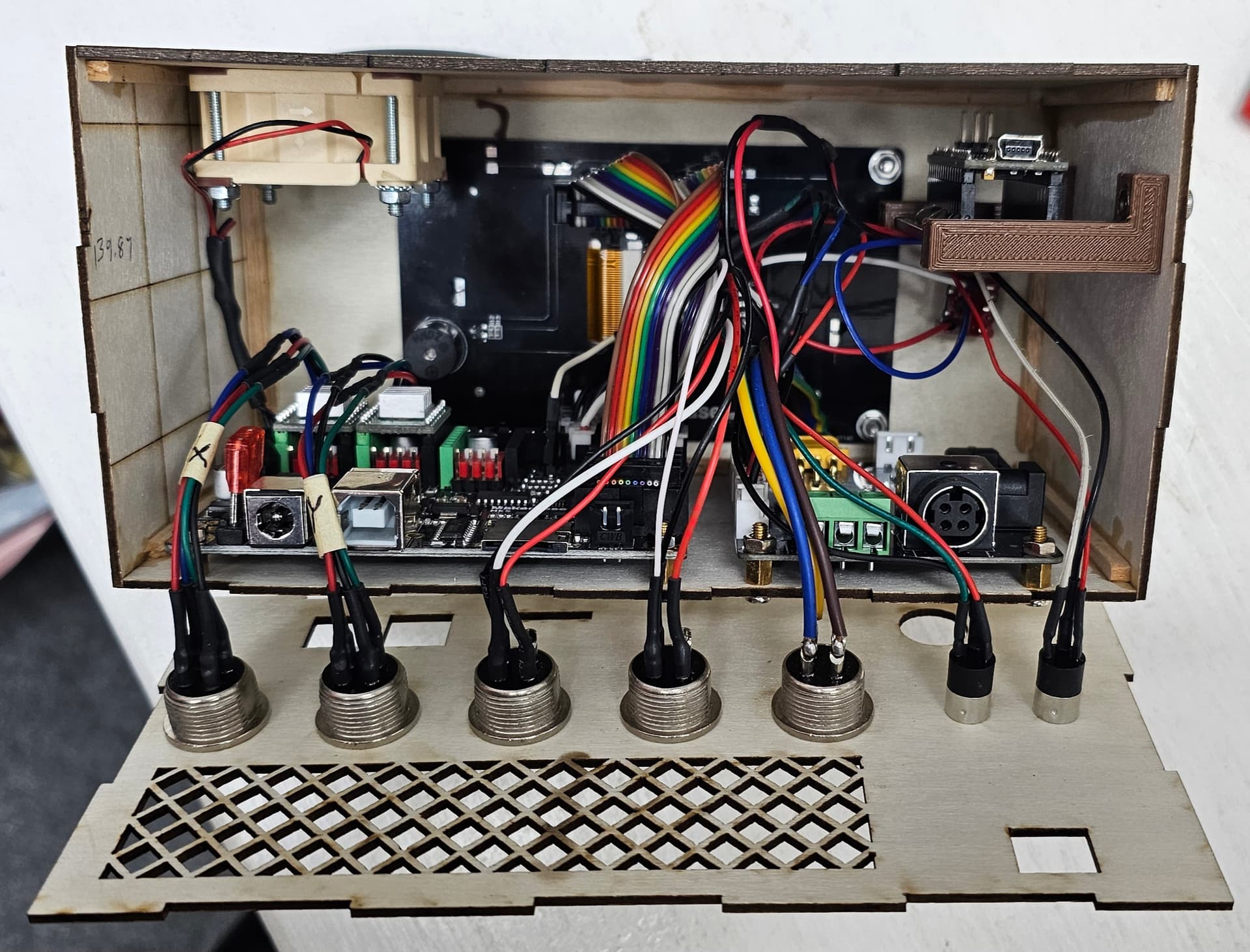
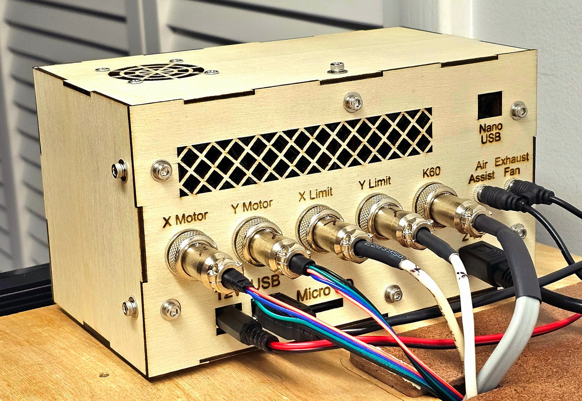
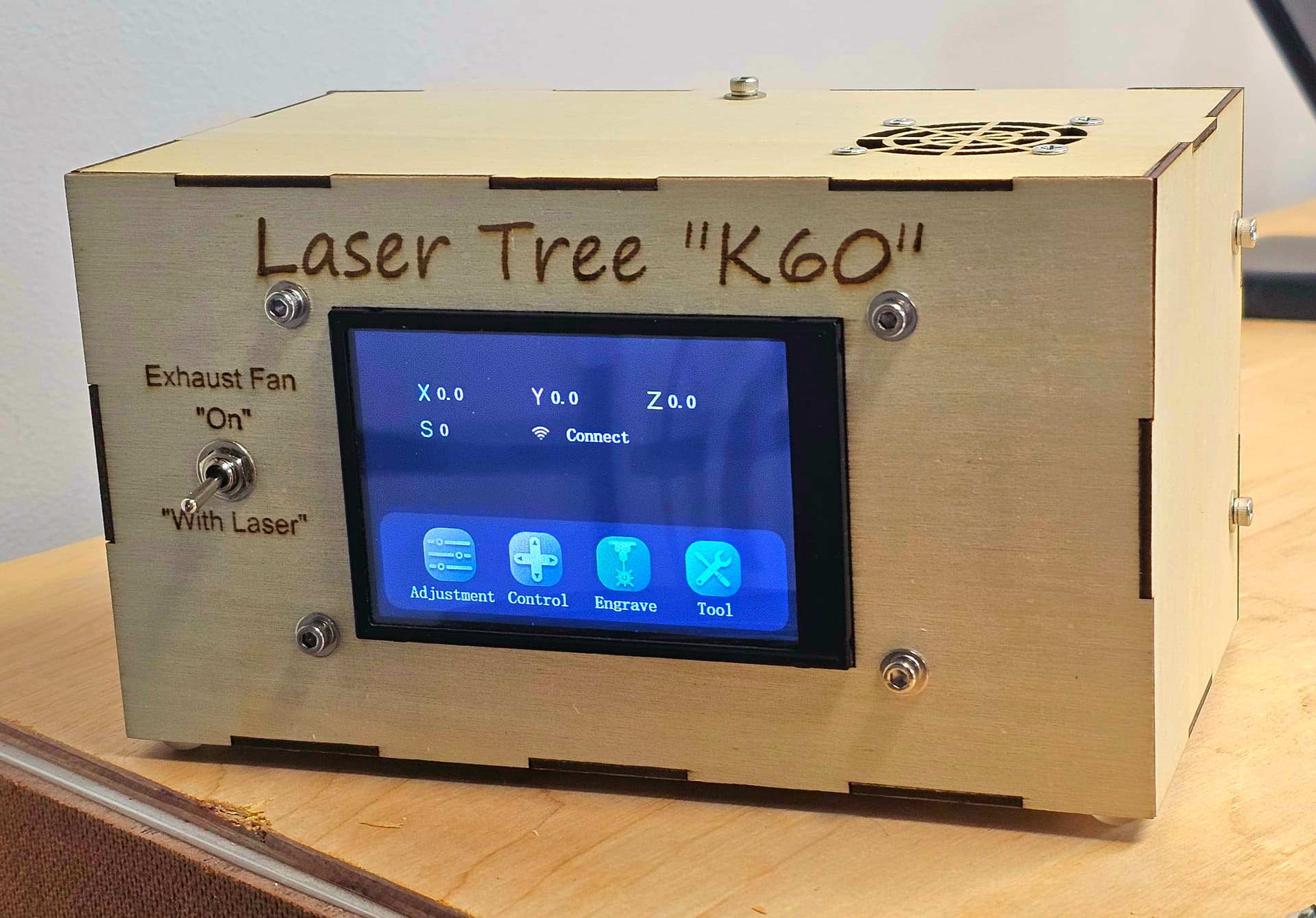
I also incorporated an Arduino Nano inside the enclosure I made that houses the DLC32 controller and the driver board for the K60 diode laser. The Nano monitors the signal to the K60, and automatically turns on the exhaust fan as soon as the laser fires. The Nano code module I wrote continuously motors the K60 signal, and waits 60 seconds after the K60 stops to turn off the exhaust fan, which is enough time to evacuate the cabinet of smoke and fumes.
For the platform circuit, I used two of the endstop switch circuit boards that came with the CNC kit. I never had the need to read the voltage on the S pins of these boards. I plugged them in, and they worked. Based on my experience with my Arduino projects, “LOW” was interpreted as a voltage below a certain point. From Arduino’s documentation:
- a voltage less than 1.5V is present at the pin (5V boards)
- a voltage less than 1.0V (Approx) is present at the pin (3.3V boards)
So based on my experience, I had no reason to believe that “S” should be connected to “G”.
Again, I sincerely apologize for any confusion created no my part. I wanted to post this to explain why I followed the path that I did. I love designing and building things. I’ve gotten as much enjoyment out of building the new laser and cabinet as I have making things with the laser. I was a software developer for 42 of my 48 years working. I loved starting with nothing, asking appropriate questions, and then designing a solution that helped others. I started with an Atari 400, then progressed upward through PC’s, a Unisys mainframe in the Air Force, a PC based Unix system for 8 years, then Open VMS and SQL server for the last 25 years in the educational arena, support 40+ school districts. So, even with many years in the technical realm, it’s still sometimes easy to go down a rabbit hole!
Thank you to all who worked to set me straight!