Just changed my x-axis motor to a closed loop. Is there any settings i need to adjust in lightburn for best operation.
There are no LightBurn settings, because motor parameters live in the controller.
Previous discussions suggest you may encounter problems from the time delay due to the servo loop around the stepper: nominally straight-line motions will have noticeable bends near the beginning and end.
Do searches with term like “servo motor” and “closed loop” to dig them up.
Ed,
Did as you stated, had to recalibrate the X-Axis to get the Steps per inch right. other than that, seems to be no issues…however after saying that, I am having issues when trying to use the extra speed. At low speeds, 100-250mm ps, it engraves great but when it goes above 250 it apparently is going to fast for the laser to hit the target. but that is to be expected with a 50w laser. As far as cutting, it works great in the same range, but as stated, anything faster and it definately looses steps in a hurry. Also still working on the Focus on the head also…that is a tough one to get exactly right.
Now during this whole process, I have done the following…New Laser head, New Lenses, New X-Axis Motor and Controller. Still waiting on the Y-Axis motor and controller to come in to replace it.
That may be the problem I mentioned: the time delay difference between the two axis motors will cause a motion tracking error.
That suggests the acceleration values are much too high. Something around 1000 mm/s² should get it into the ballpark, then tune from there.
I have a 60 W machine that engraves happily at 400 mm/s, so the problem is unlikely to be due to tube’s optical power.
Do a ramp test to find the focus sweet spot. I 3D printed an overly elaborate fixture to simplify the process:

A piece of cardboard tilted on a block will do fine. ![]()
What advantage is servos if they maximum acceleration is only 1,000mm/s^2?
My machine is current set to 45,000mm/s^2 for it’s acceleration.
Maybe a poor lps with a crud response time?
![]()
-
Have never done a ramp test. Will have to trybthis to see what happens. Be ready for additional questions for help.
-
Will have to check the acceleration settings. Not sure what they currently are.
-
May have to send you my settings to see where they can be improved.
-
Stand by for additional help…which i kmow will be needed. As you guys are thhe experts, and i am just an apprentice.
Jack…
Give me suggestions on where to start. As i stated to Ed…please stand by for questions…maybe we together can get this figured out.
It’s a homebrew machine apparently losing steps, so a lethargic acceleration should get it working. If that’s the case, tuning for best picture comes later, after it starts following orders.
Ed,
Can you email me your design for the ramp test, i can 3dprint it, and also the test page you put on the ramp.
The source is at the bottom of that blog post. ![]()
You’ll need OpenSCAD to generate the solid model after tweaking the layout to match your hardware:
Simple barebone way I do it. Nothing special, nothing to build, print, make. Just use what is laying around at hand.
Any thin piece of wood elevated on one end. Run the laser down the wood starting at high end going to low end. Been using this method for over 10 years. It never fails. Gcode example
G20G54G90
M3 turn laser on
G1 X5 or however far you want to go.. Length of wood works great.
G0 X0
M5 turn laser off
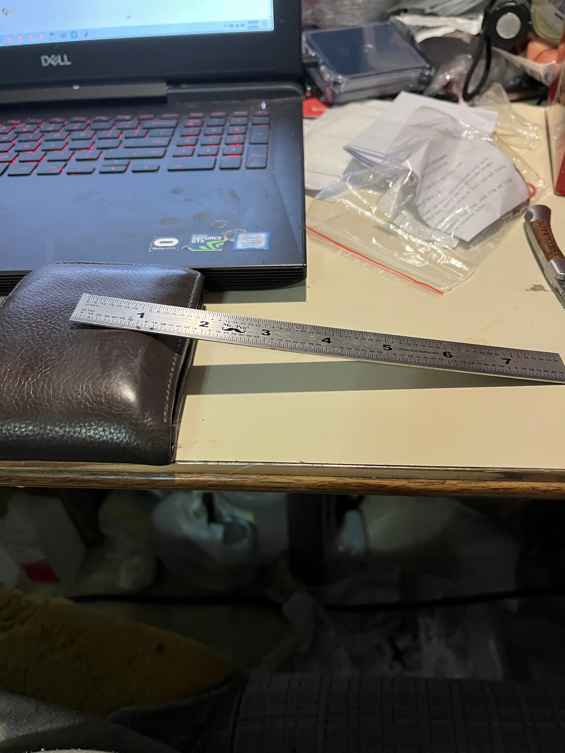
Wallet is for elevating one end. Ruler is where the piece of wood will go.