Dropping in with hopes for help with some scaling issues I’m having. I’m using Inkscape for design and importing/sometimes copy/paste into Lightburn, I have many shapes within a shape that are cutting too far apart. All nodes have been connected and shapes are closed.
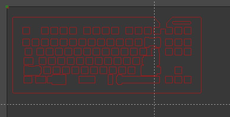
I’ve done calibrating for both axis with the 100mmx100mm method. I also dialed in the step parameters for both axis. I’ve tried converting my files to .dxf and .eps to no avail. Laser head, bed, machine as a whole are centered and level. Kerf is .2mm and I am using the Geometric Bounding Box for all alignments within my design. The smaller squares within the larger rectangle seem to have the right dimensions but the spacing between them is too wide/high.
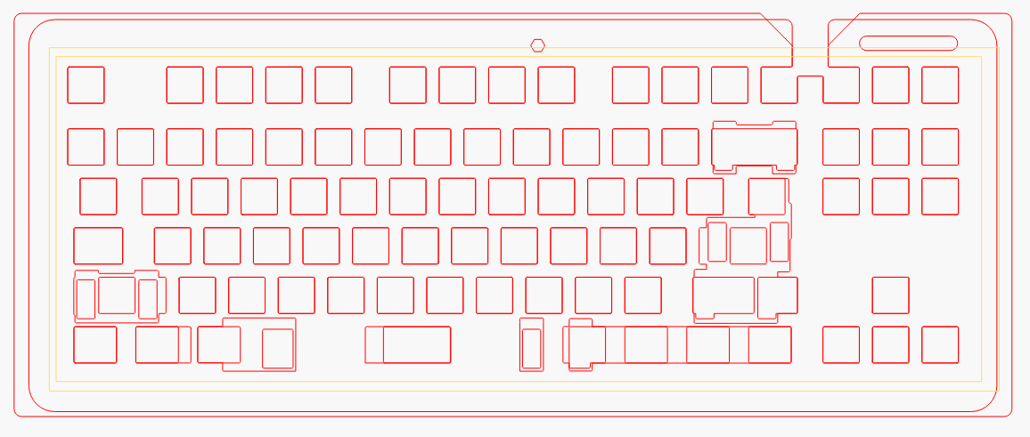
This issue seems to only come up when cutting shapes within shapes. My design utilizes many 14x14mm squares within a larger rectangle-esque shape. Any ideas as to what might be going on here?
I’ve had that in mind as well. At one point I tried compensating x axis calibration and even reduced the distance I was using between shapes of the design itself. Worked in a sense but not at all something I’d like to continue doing.
I see nothing really unusual in the file. Speeds are very much on the moderate to low end. Line operations will for sure stress mechanical deficiencies more than a scanning operation because of the rapid motion changes.
Do you hear any mechanical grinding/straining noises as you’re cutting? It could be that your traversal moves or acceleration are too high. Did the controller come with your machine? Have you changed parameters or reset to defaults at any point? If not, I’ll assume that the settings are probably okay for your machine and still likely something mechanical.
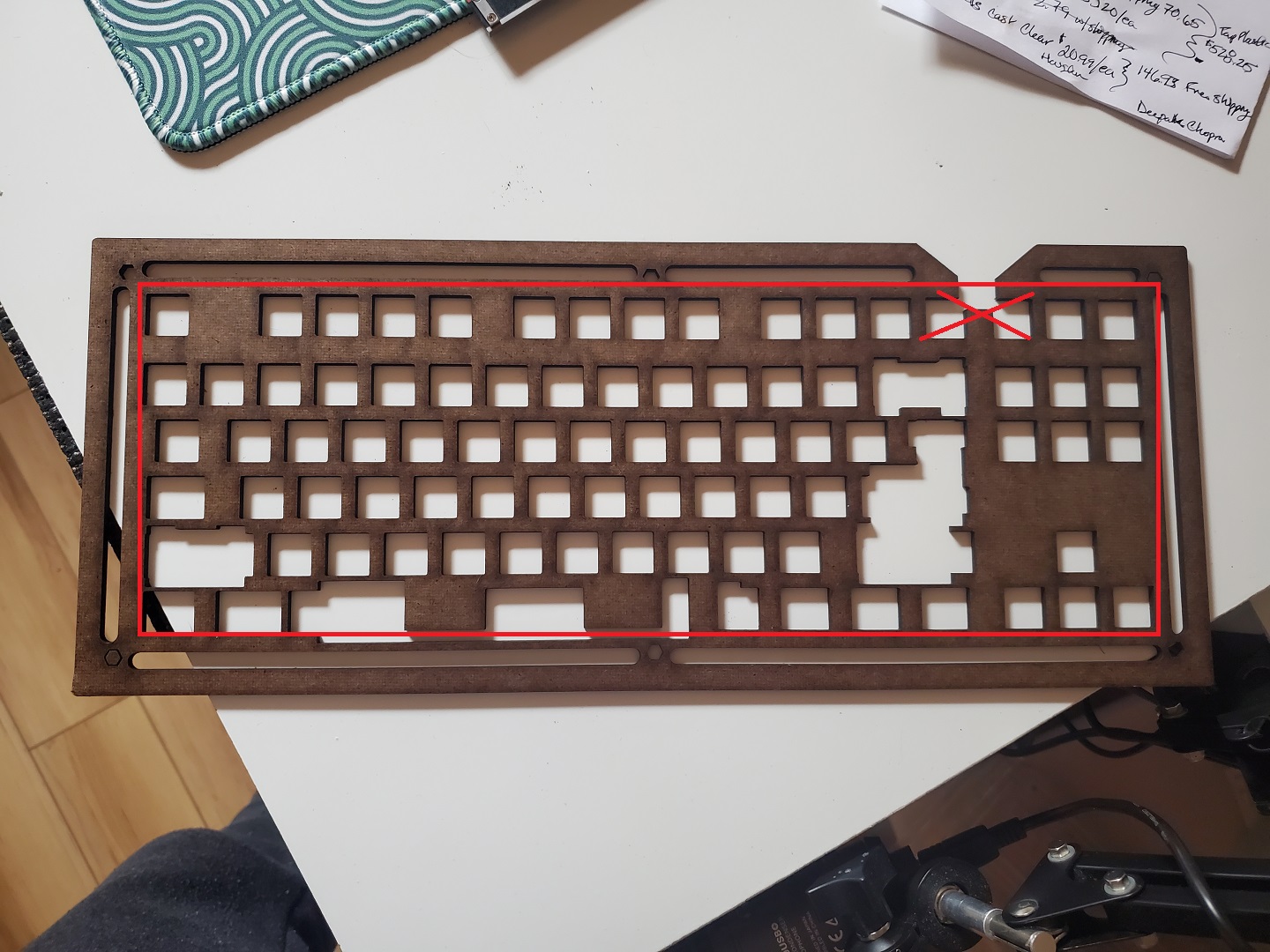
So here’s my end product. Tolerances need to be pretty tight for this application.
Also, just double checked my belts and made some slight adjustments to no avail. I’m not hearing grinding or any other sounds that would indicate excess friction. This conroller did indeed come with the machine. I’m running an Omtech 55w 16"x24" and haven’t quite dug into factory resets and the like. Have not adjusted acceleration setting either.
Edit: lbrn file, screenshot, and picture are all of the same design and have identical measurements and were cut with all the same LB settings - just different layouts of what I’m cutting.
Oh my bad. Edited and re-uploaded my last photo but here are more details as to what’s going on:
These designs have been cut with Ponoko at one point or another and have always turned out well. Translation to my machine however seems to show a gradual shifting of all squares to the right or left to a total of about 1mm off by the time we reach the outermost square cutouts. The first few columns of cutouts seem to align and then gradually the shapes are shifted outward on the X axis. Y seems to be fine.
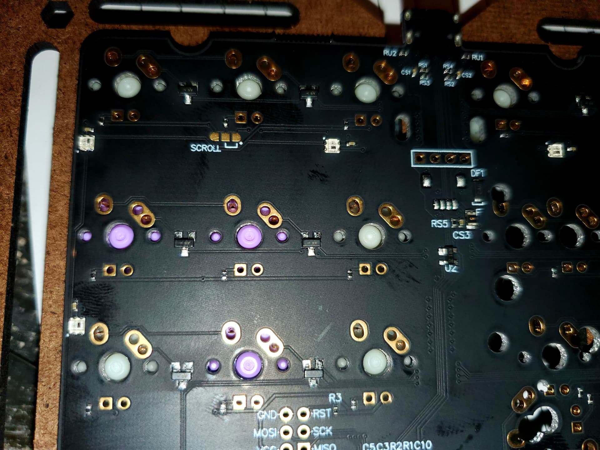
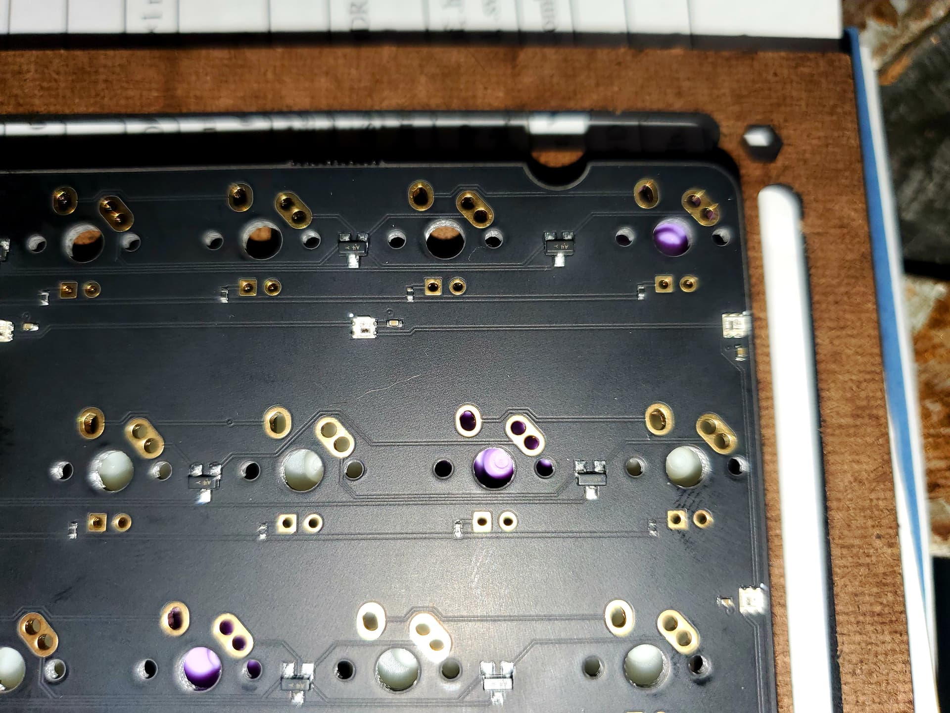
Might look a bit technical but here are images of the piece in action for more context. First image shows the aligned side and second image shows the more pronounced shift in shapes that are causing misalignment with my parts on the opposite end of the group of squares. Again, the offset of these shapes from either left or right is gradual and the last square cutout shows a final shift of about 1mm
I’ve changed the orientation of my design to no avail which is why I didn’t settle on this being a mechanical issue. I’ve cut the design in 3mm hardboard, 3mm acrylic, some .1ish impact modified acrylic all with the same result.
Meant to add this file to the reply. It’s a comparison between the oldest version of the design that I’ve had cut with Ponoko dozens of times compared to the more recent revision. The small square cutouts were essentially imported from the original design and as you can see, those cutouts align perfectly: P87SPLBForum.lbrn2 (145.8 KB)
Are you saying the offset follows the design, not the axis? So instead of seeing a shift on the X axis you see it on Y axis when you rotate the design 90 degrees?
Is the resulting engraving always exactly the same offset? Or does it ever shift?
What format was the file that sent to Ponoko?
I’ve overlayed the old and new designs. Are all the differences intentional in the design? I assume these aren’t the issue that you’re seeing.