Hi, im trying to figure ramp settings on my Co2 Galvo. I can see that with a gantry you adjust your min/max settings to achieve this setting. But i dont see any min/max settings for the Galvo settings. I can adjust the ramp fine but what im getting is a line around the vector thats actually deeper as im guessed its not adjusting the min power for the ramp. Any advice to get the ramp using this machine? Using rubber and trying to make stamps with tapering off edges. Many thanks.
1 Like
Share a few screenshots, showing the workspace with the art, the ‘Cuts / Layers’ window, along with the ‘Cut Settings Editor’ (double-click to expose), so we can see what you are starting with. Also show us what this looks like in the ‘Preview’ window, along with the results when produced on your material. ![]()
2 Likes
Cloudray rubber
Ai file
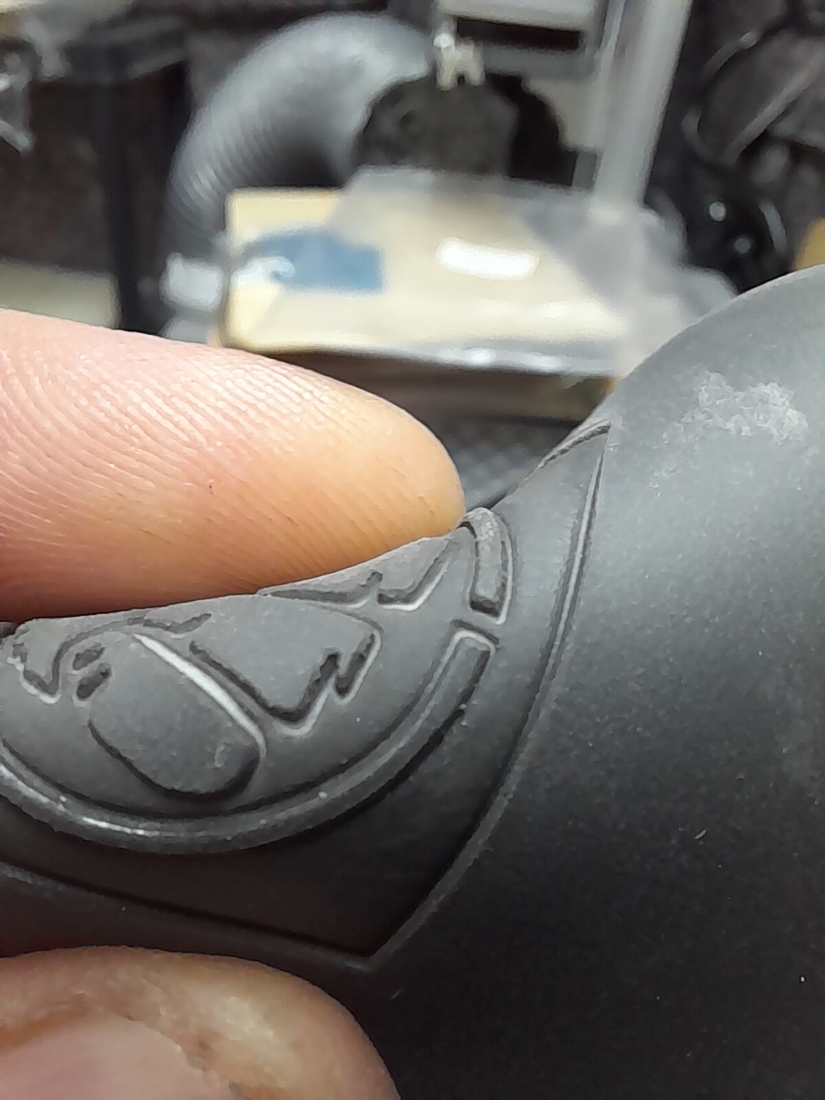
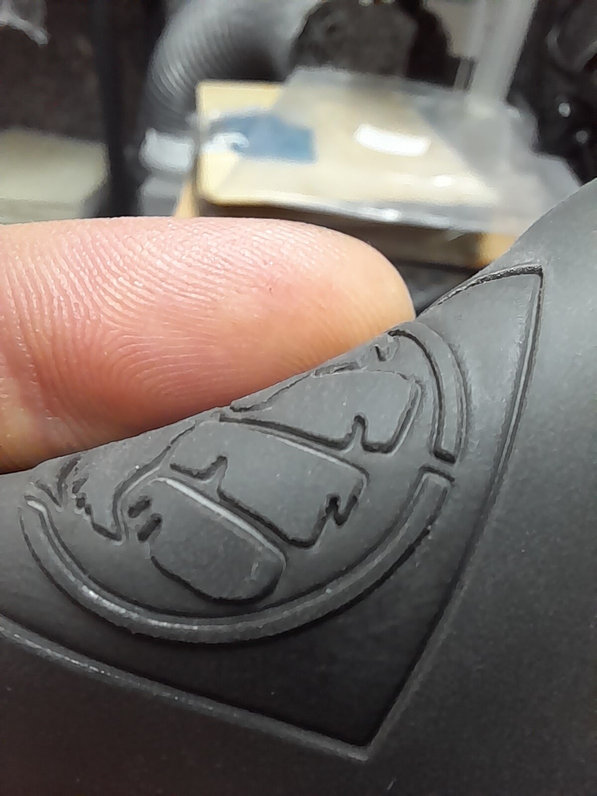
Pics below. Notice the deep cut around the image.
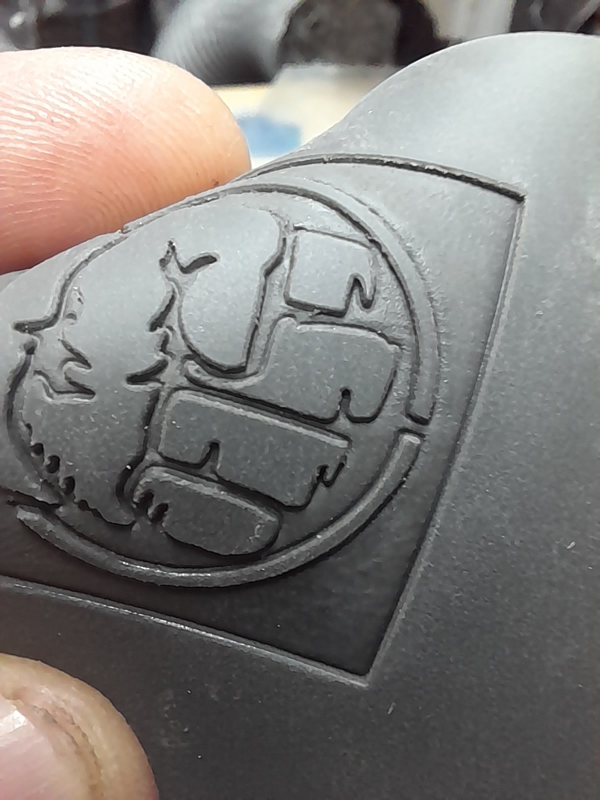
Looking to achieve something like last image if possible, understand that the example is done on a gantry. @Rick


For Galvo (and GCode) devices, the minimum power used for Ramps is 0%.
I believe the edges you’re seeing are due to an interaction with your Galvo’s Timing Settings, which are meant to prevent over or under burning when your laser speeds up or slows down. In this case I believe those delays are leading to relative over burning at the beginnings and ends scan lines. The power is ramping down, but the laser is dwelling too long, making those lines around the edges.
In the Cut Settings Editor, try clicking Show Timings, toggling on Override Default Timings, and setting Laser On TC and Laser Off TC both to 0.

Thank you. I’ll give this a try. ![]()
Can you further explain your statement for turning off the start/end TC timings?
I changed these to align the scan lines. Would this not make bi-directional scanning not applicable?
I thought this aligned the bi-directional scanning start and end times.
Thanks
![]()
On/Off Timing settings are meant to prevent power output “pooling” as the laser accelerates or decelerates at the starts and ends of scan lines.
For On, if a delay is too short, you’ll see thicker lines near the beginning. Too long, and the scan lines will be shorter than they’re meant to be. For Off, the reverse is the case.
If they’re incorrect, you should expect to see defects with either Bi-directional or Uni-directional fill. But the defects would alternate sides of the scan lines if you have Bi-directional enabled, versus appearing on one side only with Uni-directional fill (although, if both On and Off timings are incorrect, you could see similar defects on both sides in this case).
Overriding Timings as I suggested above is for special cases only. Usually, the Timings that are imported from your EZCad2 configuration are correct in the majority of use cases. If you’ve found timings that are working well for you, stick with them.
Thank you, this has stopped the deep cutting. Much appreciated.
3 Likes
This topic was automatically closed 30 days after the last reply. New replies are no longer allowed.