Co2 laser cutting doesn't smooth

Hi,
I have and DIY Co2 60w laser. And I installed a mini GRBL controller from awesome tech with lightburn. After assembly I see that cutting lines aren’t nice flat and smooth, are “toothed”.
When laser cutting straight lines, the cutting edge looks good, without any defects. But in cuts where works both axes together (X and Y) cutting lines go toothed, for example cutting circles, they are ~50mm diameter. Not so small.

  1. Gantry is squared
  2. Motors are nema 17 with external drivers. I tried to change the step/pulse in drivers, the result goes in the wrong direction. Now it is 25600 pulse per rev.
  3. Belts are tight. We tried to release a bit, nothing changed.
  4. Possible to feel some “vibrations” when all axes moving.
  5. Cutting speed 10-15mm/s. Tried with 5mm/s nothing changes.
  6. Mirrors are mounted tight.
  7. All other stuff like an air compressor or air vent is not in the same frame.
  8. Table is mounted tight.
  9. Hiwin Rails.

I’m attaching some photos how the cutting edge looks like

1 Like

That’s an artefact from the laser pulse, not cnc hardware

Check awesome tech for tuning recommendations on the laser control side

You might also evaluate the capacity of your power supply supporting your stepper drivers and motors. It’s a shot in the dark on my end, but maybe when you’re running those two axes together there is some sag on that PSU.

Another check would be on the holding torque and acceleration settings.

And one last suggestion in my head right now is to confirm you have the driver DIP switches set appropriately for the current recommendations of the motors.

Thanks, guys for a fast response.

Today made some changes in settings and a few changes in hardware.

  1. New controller location, further from co2 laser power supply and other electronics. Nothing changes.

  2. Made some changes in DIP switches - current and pulse/rev adjustment. Nothing changes in cutting quality. Now it is on 8000 pulse/rev and 1.4A current output. Was on 1600pulse/rev and maximum current ~5.6A. No changes in cutting quality.

  3. New power supply for motor drivers - 24V 15.5A Output. On the power supply output connected only stepper drivers, no other devices. No changes in cutting quality

  4. Controller is connected directly to USB, without any other ports.

  5. Increased and decreased drastically acceleration and MAX rate for both axes. No positive and negative changes in cutting quality.

  6. Steps per mm also have no effect on cutting quality.

Also, I have seen, that laser not engraving, X and Y axis is moving but the laser tube not turning on.

On the Y-axis is mounted 2 motors!

Using those NEMA motors:

Using those drivers:

I’m attaching some photos of settings,

Having two motors drive one axis has some risks associated with it and could be a contributing factor to the result you’re having.

Mounted one more stepper on Y-axis. Now are 2 steppers for 2 motors. Sadly, but no positive change in cutting :frowning:

I think you misunderstood - 2 steppers on one axis is problematic.

Can you make it so theres only one?

Even big industrial lasers use only one - for a reason. When you’re working at millimetre precision, a slight difference in synchronisation between steppers introduces artefacts - such as you are seeing.

Good news! Problem is SOLVED!
The problem was in stepper drivers. Previous stepper drivers was too powerful for that motors. I think the problem was in stepper driver current settings. Mounted other stepper drivers, with 0.5A minimum output power (previous stepper drivers minimum current output was 1.4A). And laser now works perfect :slight_smile:

Both of their minimum output is 0A - a stepper with a minimum >0A wouldn’t be much use as it would be energised constantly.

I think the problem was in stepper driver current settings.

The problem with too much current is that the driver can drive the stepper in excess of it’s ability to get rid of heat, and it will burn out.

The problem with too little current is that the driver can burn out before it exceeds the capability of the stepper, again due to being unable to get rid of excess heat, and in missed steps due to mechanical inertia (the gantry has mass and takes time to stop or change direction - if the driver isn’t powerful enough to arrest the movement and change direction before the next pulse is issued, you end up with missed steps.).

I suspect the more likely cause is machine resonance due to incorrect microstepping.

People misunderstand microstepping, thinking it makes their machine more accurate - and in some respects it does: Your stepper is designed for 200step/rotation- 1.8deg/step. Your machine is geared to move 25mm/rotation, or 0.125mm/step at 200steps/rotation, therefore the smallest movement you can make without microstepping is 0.125mm.

If you change your microstepping to 4 micro steps, your smallest movement possible is 0.125mm/4 or 0.03125mm, at 8 microsteps, your smallest movement is 0.125mm/8 or 0.015625mm - both are more than accurate enough for anything other than the most demanding cutting job when your cutting ‘head’ is ~0.01mm wide.

The tendency is to set your machine to the highest microstepping your driver can achieve, but that can introduce artefacts due to ‘chopper’ drivers having non-true-sinusoidal torque curve - your resolution increases but accuracy actually suffers. All chopper drivers have high-order harmonics that distort the curve and affect accuracy. They also all suffer from electromagnetic backlash (moving forward or backwards to the nearest ‘true’ stepping point of 1.8deg). 3-pole and servomotors suffer this less, if at all.

the best microstepping is the one that gives you the closest resolution to the level of accuracy you need.

If you went to 16 or 32 or 64 microsteps, that can cause harmonic stutter as the stepper ‘hunts’ to find the closest natural step to rest at.

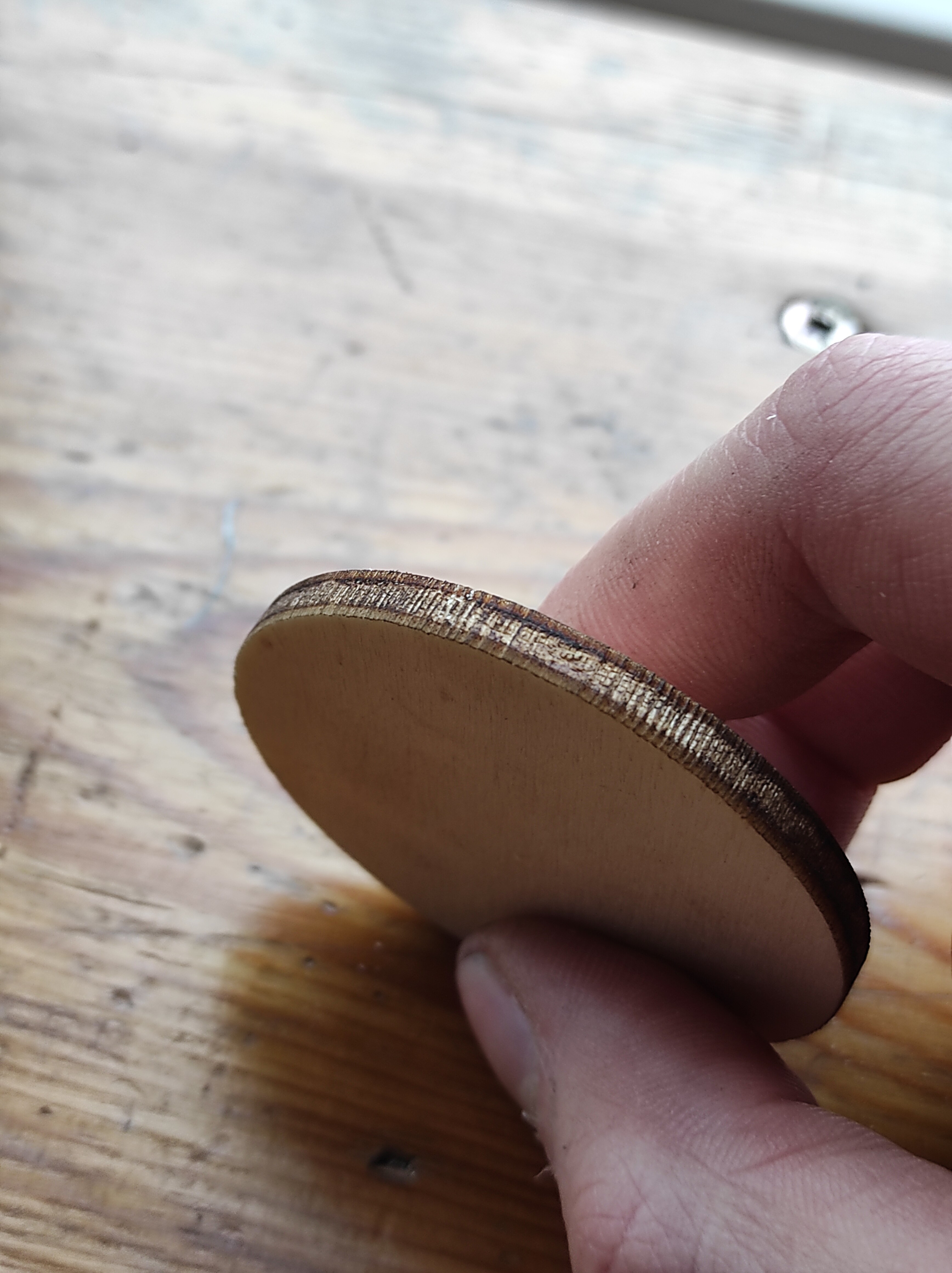
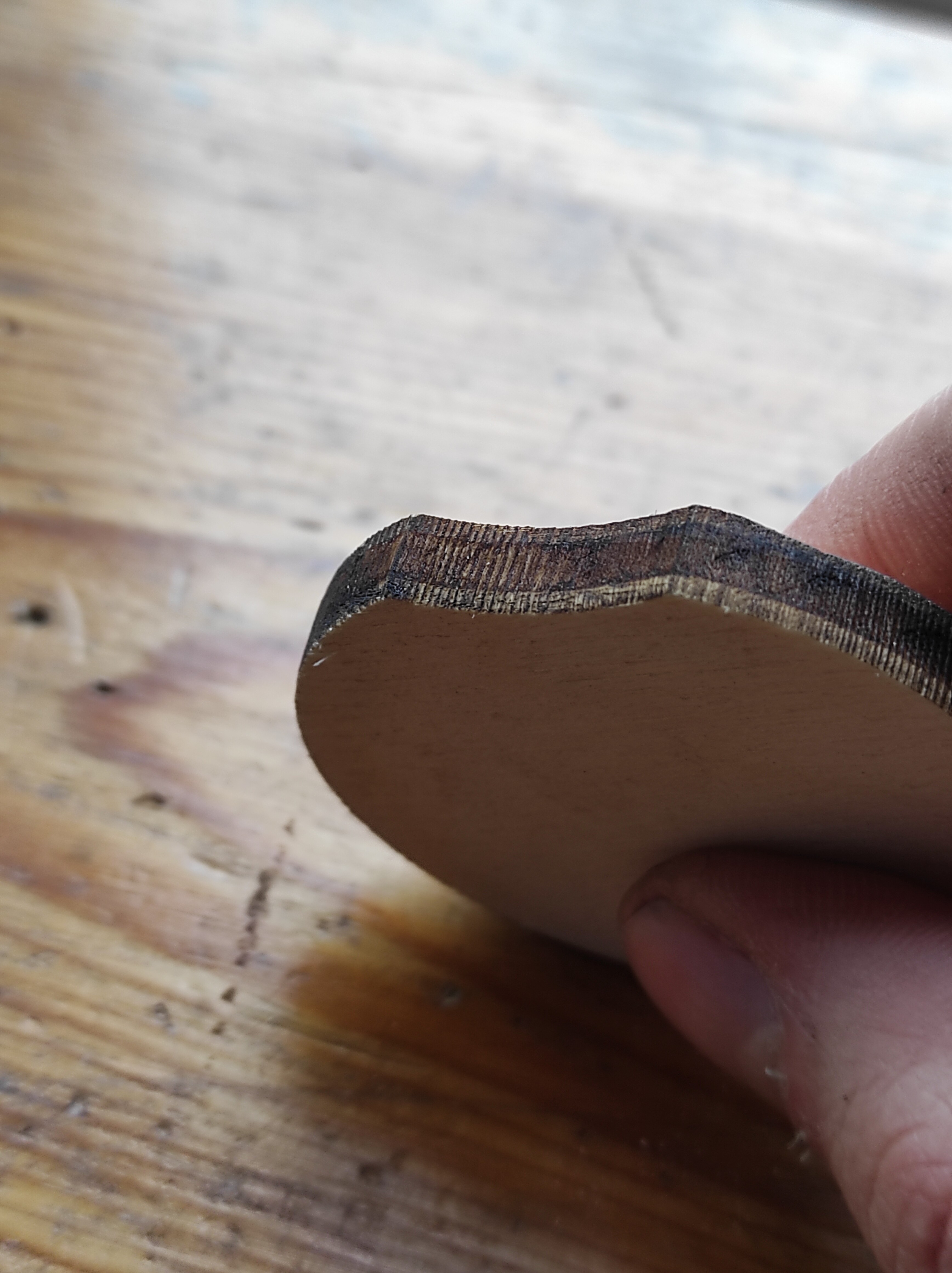
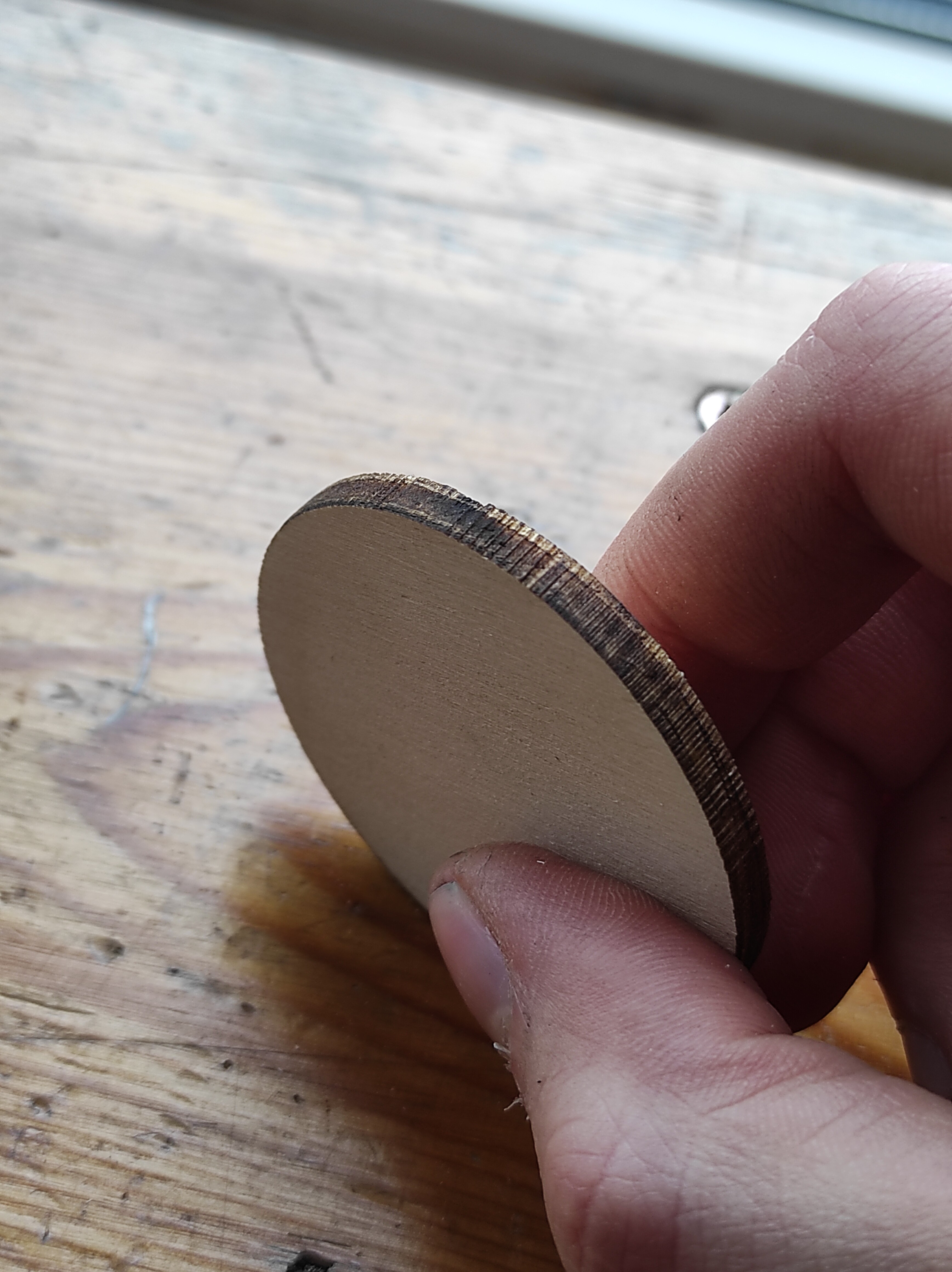
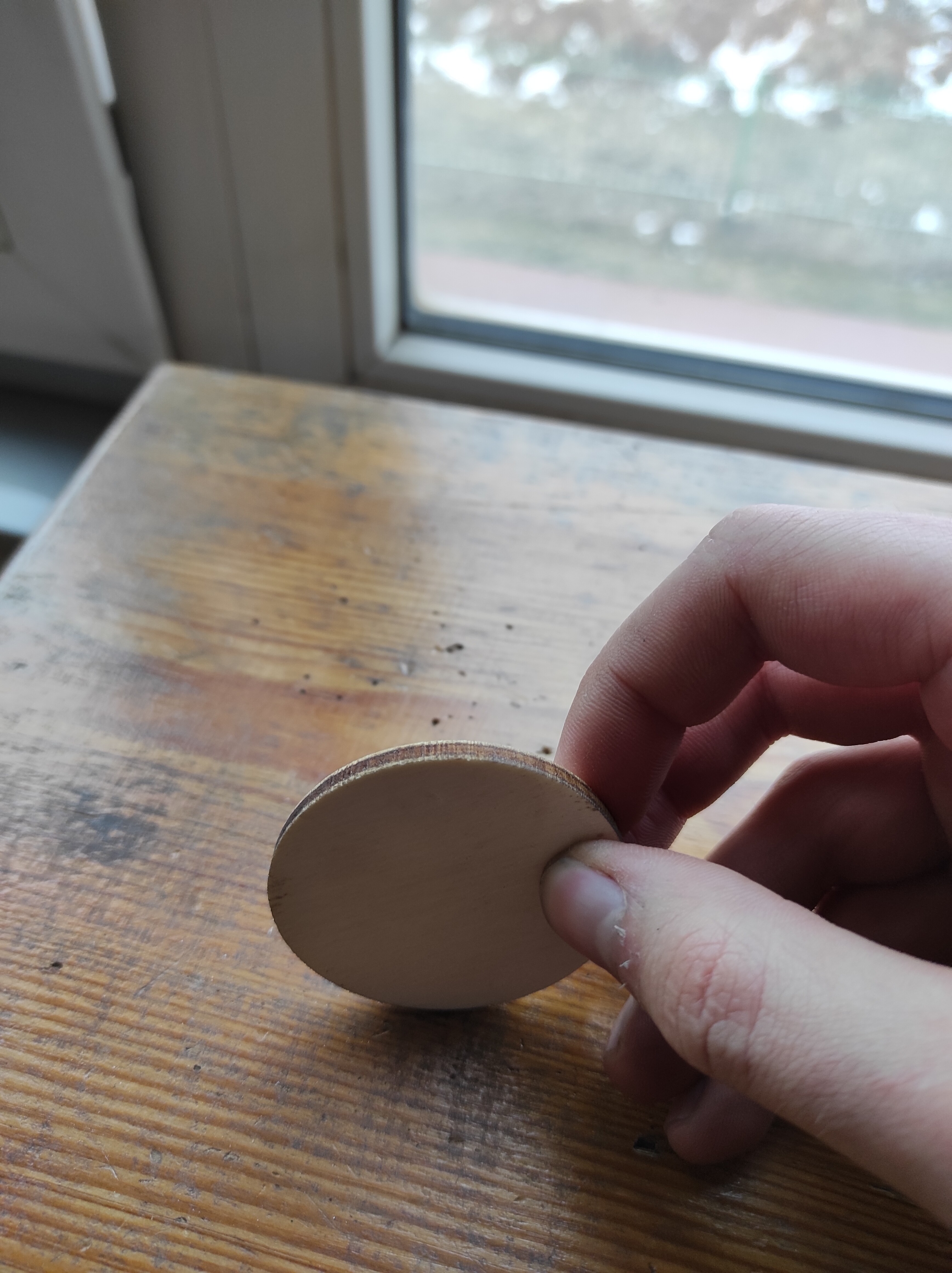
That’s what your picture looks like. Harmonic ‘stutter’ due to too high a microstepping setting.

When considering a new machine design, we look at the maximum travel, and maximum desired speed. You pick a stepper motor with the capability to deliver that and pick a driver to suit. When deciding on accuracy, you pick the resolution that you require within the gearing of the CNC parts you have decided on. You do that by issuing, say, 200 steps (a full rotation), measuring the distance that you move, dividing that by 200 and then deciding on the microstepping you will need to achieve the resolution your machine needs for the accuracy you want to achieve.

Choosing the pinions you use will determine the final gearing - just like changing gears in a car determines how much progression you make per RPM. It’s a fine balance of gearing, steps angle, and microstepping.

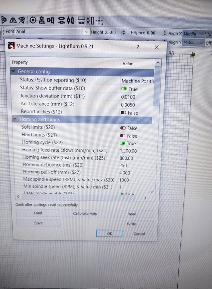
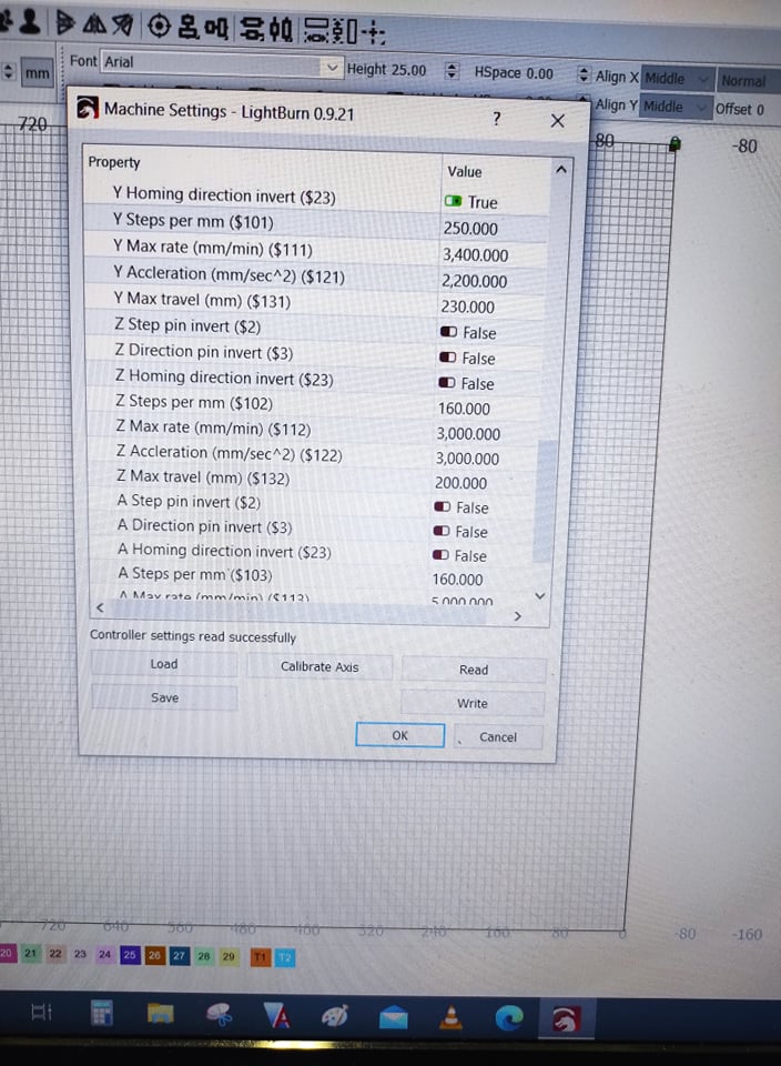
Your settings were 250 steps/mm - 0.004mm/step. Do you need 4000th of a mm resolution?

2 Likes

very interesting reading, thanks Bo

Thank you for your reply. That makes sense.
But… here are some points about nothing talking, or I’m not found some information.

First of all - Lightburn after axis calibration calculating steps how much need to move axis for a selected distance. And light burn fill steps per mm automatically. Those numbers are made by light burn itself, we just slightly modified, because the axis was not moved exactly in the same distance.

Second, on previous stepper drivers, we selected the smallest amount of step/pulse, which was 400. After that cutting line was getting worse.

On the new stepper drivers, on Dip switches are on 1600 pulse/rev, and cutting quality is perfect.

And after placing the new stepper driver. After axis calibration Steps per mm drops from 150 to 41 or 42 steps per mm.

1600 pulse/rev is either 8 microsteps or 4, depending on whether you are running a 200 or 400 step stepper

Which lends credence to the fact you had the wrong microsteps set.

the bit at the end:

Wasn’t really questioning your settings so much as pointing out that if you don’t know what you want, how do you know how to get it.

You masked your problem by replacing the hardware and it fixed it, but I’m not convinced it had anything to do with power/amps. It looks all the world like a stepper/CNC/driver mismatch in settings.

My X-axis is set to 4.7uM - so 0.0047mm - it’s not an unusual number for a Ruida with decent steppers and drivers, although I’m using hybrid closed-loop 3-phase steppers, rather than regular 2-phase.

This topic was automatically closed 30 days after the last reply. New replies are no longer allowed.