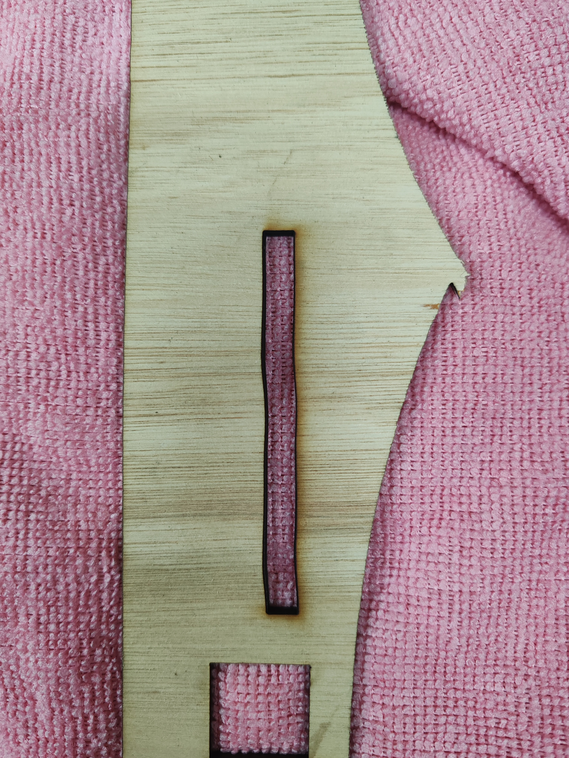
So I recently built a co2 laser. But am having a little trouble with to parts first is the beam It does not seem as strong as it use to be. The second as you can see from the photos is the noticeable wobble on the y axis. I’ve alined the X axis for the beam and have the setting at 10- 20mm per sec on the high end along with retighting the belt.
I’ve been able to cut regular 3mm plywood in the past.
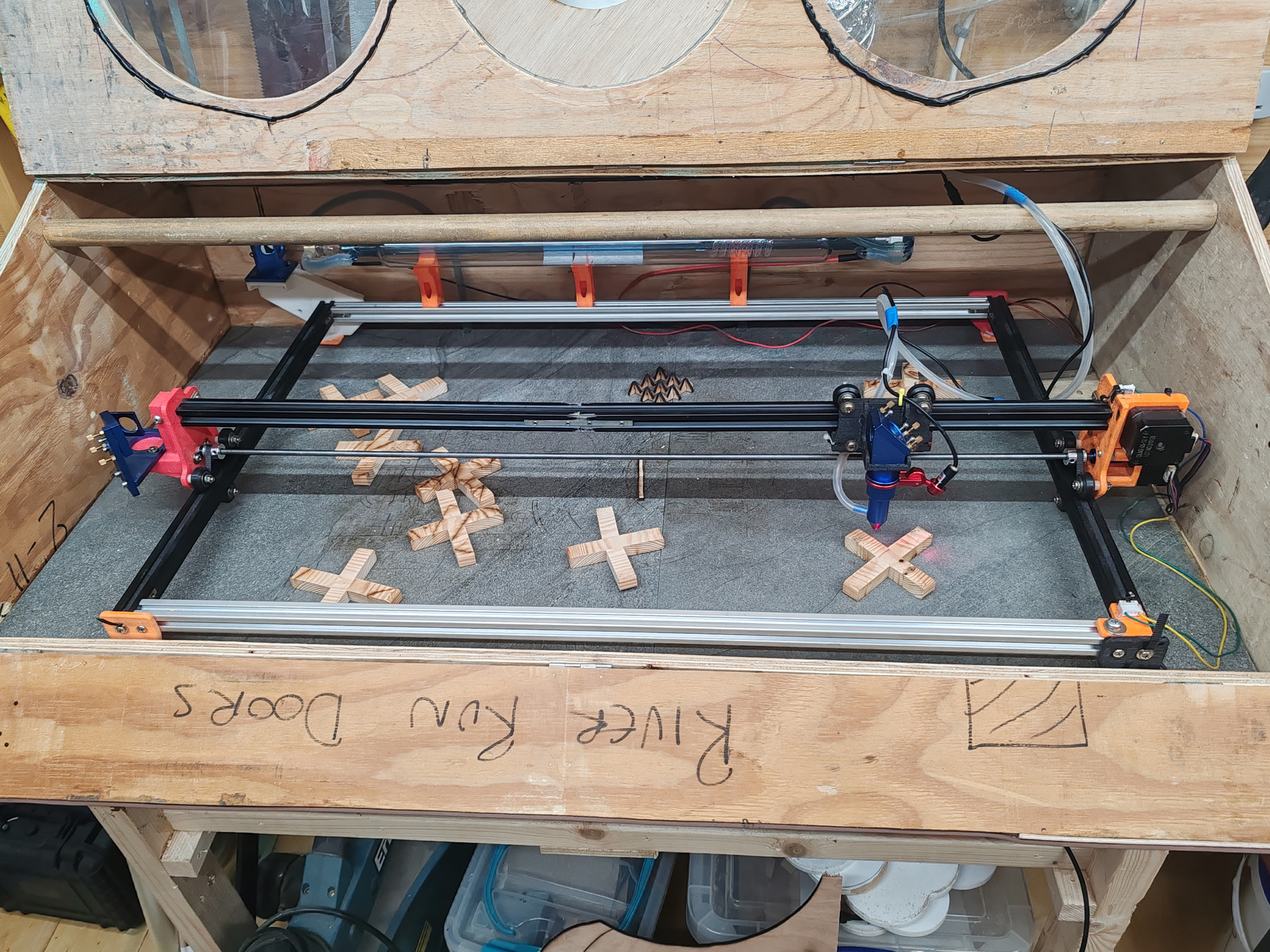
The wobble is most likely caused by your x-axis design. To be honest, that looks a bit… temporary. Change the profiles to a single one. It doesn’t even look straight. Then, better not use wheels; use a linear rail. Using the wheel design, you will never get perfect straight lines, since there is ALWAYS wobble in it. It’s exaggerated by the path the laser travels downward.
A gantry that wide should have dual steppers for the Yaxis. That tiny cross rod can easily permit torque twisting from one side to the other. Any dirt or resistance on one of the rails will exaggerate the issue.
If the gantry hits a low resistance area, the slave side might suddenly catch up causing that zag in the middle.
The splice between the gantry extrusions seems to have a significant droop that will affect both the focus and the beam angle as the carriage crosses it. If those extrusions don’t meet exactly, the carriage will rock over the discontinuity and create irregularities much like the picture.
The mechanical strain from the air hose and red-dot cable is concentrated at the nozzle, far from the carriage wheels, where it has plenty of mechanical advantage to push the entire laser head. Any looseness in the head or the rollers carrying it will show up as the X axis moves.
The long jackshaft rod seems to have a gentle bend that will affect the rotational speed due to the unbalanced weight as it turns, particularly at high speeds, and affect the Y axis motions.
Although I’m a big fan of 3D printed parts and built an MPCNC a while ago, pretty much everything looks undersized to maintain alignment under the fairly heavy loads a laser will impose. Plastic is, pretty much by definition, bendy and thin sections are too flexible for motor / bearing mounts and suchlike.
Replace all of the extrusion joints with metallic parts, replace the splice on the gantry with a single extrusion, add metallic load-bearing plates to the plastic parts, and it’ll become much more stable.
I have a 1.6m x 1.0m machine and tried to 3D print the #2 mirror holder out of PPA-CF.
It went horribly out of alignment when #2 mirror warmed up, so much that it missed the carriage entirely when it was on the far side of the machine. It actually had another issue that caused the laser to heat the mirror, but, lesson learned-
As much as I love FDM, the thermal expansion coefficient of the resulting print is problematic for this application. Maybe it would still be tolerable on a smaller machine.. And the mirror shouldn’t be heating that much. On the other hand, this was PPA-CF, a high temp filament whose shape should generally be stabilized by the carbon fiber fill. And the magnitude of the problem wasn’t anywhere near tolerable.
This posting made me very curious about the plastics. I found a very interesting website talking about thermal properties of plastics. I ignore my 3D printer, but I was wondering if any of the plastics described were available as filaments.
If they’re wired in series to ensure they have the same current = torque, then the power supply voltage will be far too low for the motor driver to manage the current for correct microstepping.
If they’re wired in parallel, then the motor driver must supply twice the current to achieve the same torque. Unfortunately, single-board GRBL-ish machine controllers typically have small stepper driver chips with maximum current less than you’d need, with barely enough heatsink capacity for the normal currents.
Although, thinking in this if my problem is the width of the machine moving each side. If I were to swap the x and y axis the would cut down on the distance of the slave motor.
If that were a solution, I suspect the manufacturers would be doing it. You would just swap the wobble to the Xaxis, right? In my opinion it is another
Bad Idea™.
You need a controller board with dual Ymotor sockets.
Typical NEMA 17 motors need 1.0 to 1.5 A to develop their rated torque. If you can figure out the maximum current limit for the stepper drivers on the board and that limit is over 2 A, then you can try:
Wire the motors in parallel, connected so they turn properly
Crank the stepper driver current to 2 A on that axis
See if it behaves properly
If the motors stall, reduce the acceleration for that axis until it can run at a reasonable speed.
If the maximum speed or acceleration isn’t high enough, the motors need separate drivers; DM542 drivers are cheap. Some GRBL controllers have separate STEP/DIR outputs for outboard stepper drivers, but they’ve been cost-reduced off that board.
A more general-purpose CNC-ish controller with outboard stepper drivers may be more suitable for an increasingly complex DIY laser, but it will put you at the foot of a very steep learning curve.
OK, wait. You CAN wire two steppers to a controller step/dir pair. This is often done with CNC gantry axes, but it does come with a downside that they can be a bit out of sync and the controller can’t correct it since it’s impossible to move the motors independently.
But hooking 2 motors to an actual power drive output"? The A+/- B+/-?
Hard no. It’s horrible. These are not resistors, the back EMF of the motor happens in the motor. So in parallel there’s no controlling the balance of current and dividing it up. Both motors go unstable. Going with a larger drive current could burn them out, since there is no control over which motor actually gets the current.
And these are “smart” drives now, that do DSP and try to control the field with code to get the motors to run at high speed and smoothes out fhe resonant speeds. That logic will be very confused at the nonsense readings for motor phase current and/or BEMF it’s trying to take.
If you can find the controller’s step/dir you can jump a second pair off it to another motor drive.
We’re in violent agreement, although it seems the early RepRap / RAMPS 3D printer designs came down hard on the other side.
I crawled through why series connections didn’t work when I saw what was going on with the MPCNC connection:
The back EMF is impressive:
For Old School stepper driver chips found on cheap controllers at the typical speeds for low-end 3D printer / CNC / diode lasers, well, it’s not as awful as it could be.