Thank you - let me give that a shot.
I know you’re off-line but here’s how things unfolded…
On a hunch, I disconnected the air pump and water pump from the external cabinet outlets (and plugged them in to a wall outlet). When I booted the machine the error led went away and I had control of the X and Y-axis again. Yeah! Even minor victories at this point!!!
Here are the results from mirror 2 test (near, far, & closeup shot).
And here are mirror 3 test (near, far, & close-up shot)

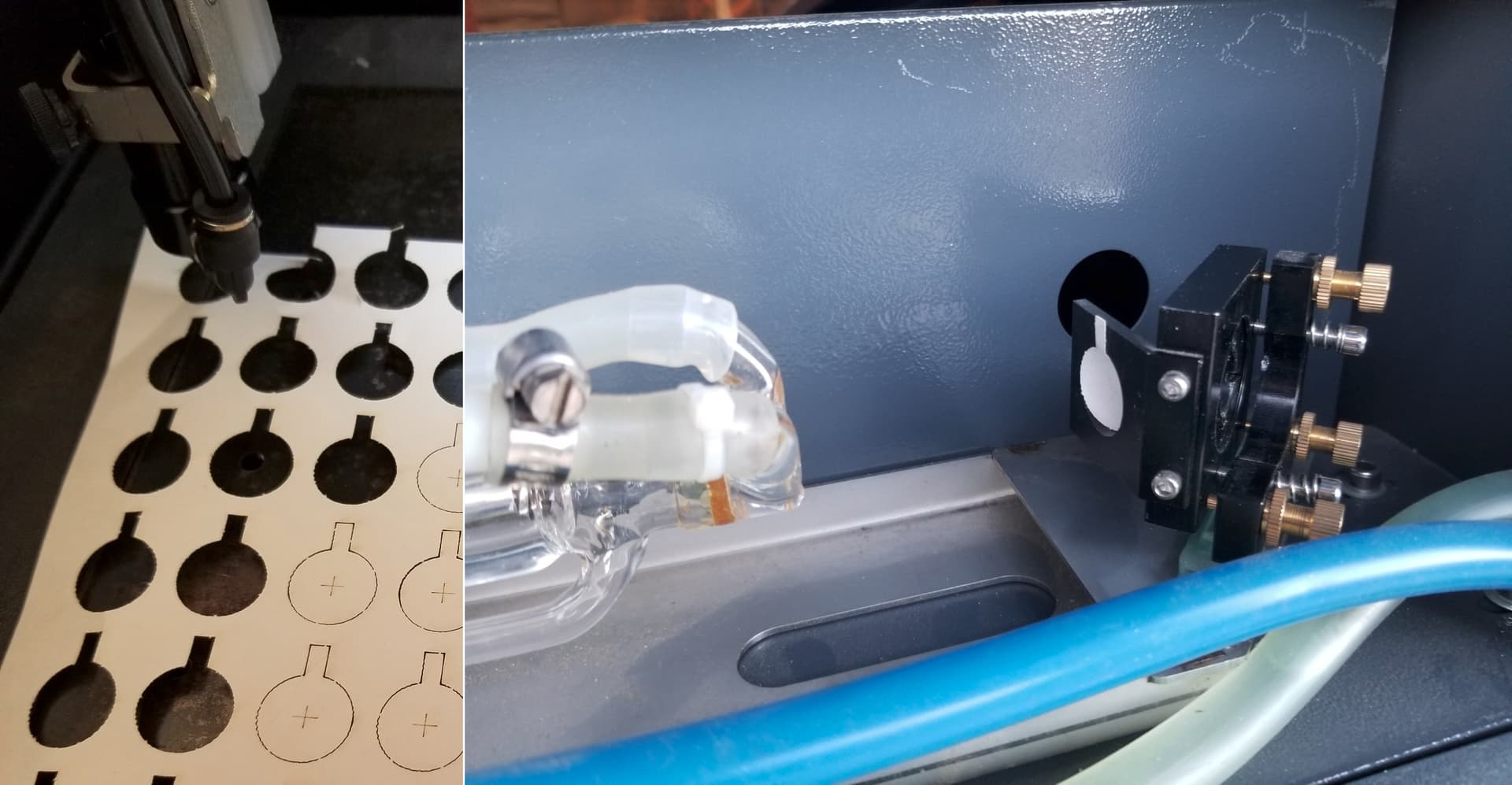
And here’s the nozzle test

So, I set both the min and max power to 75% and increase my speed to 15mm/s.
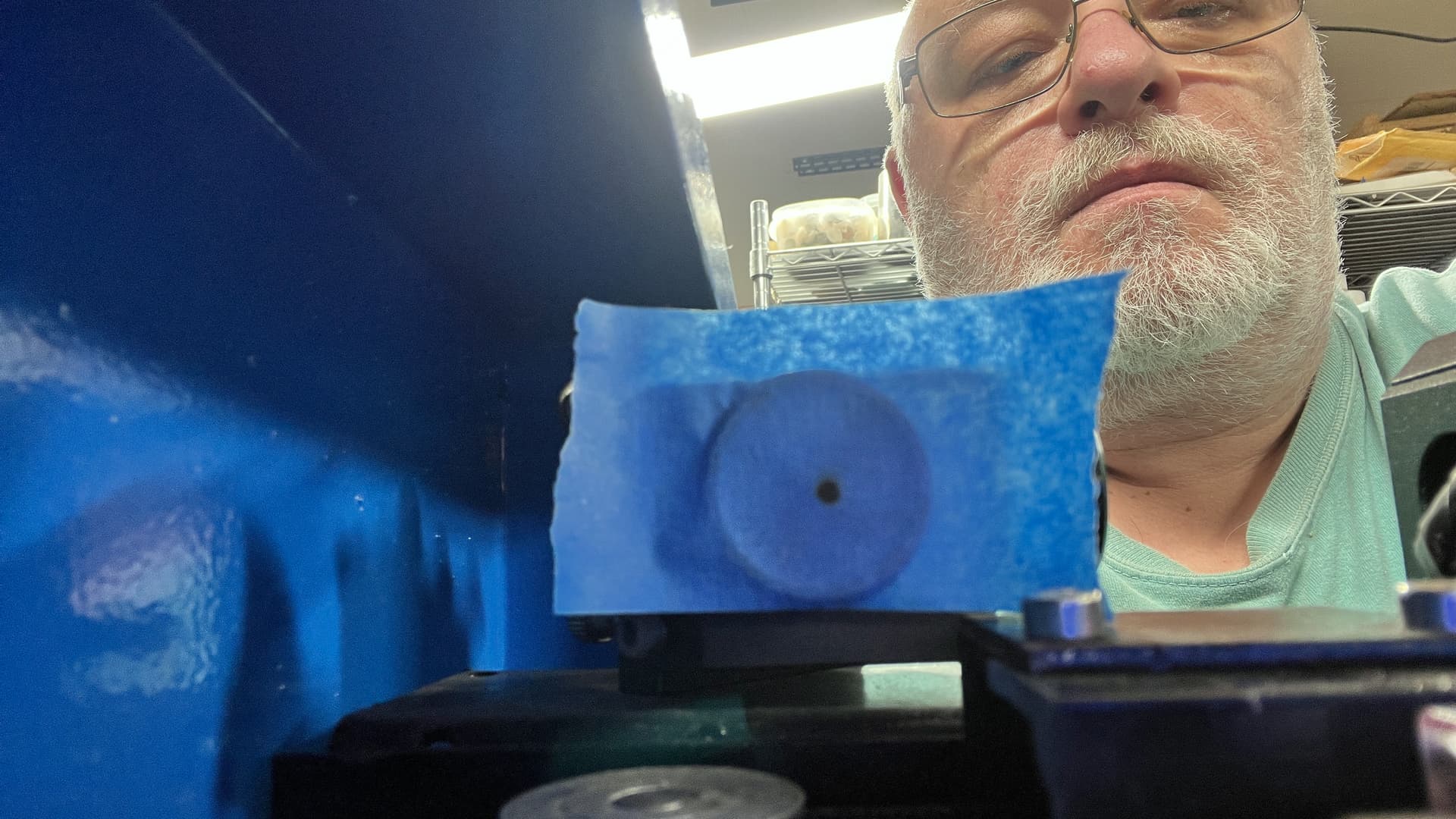
Round circle test (side A):

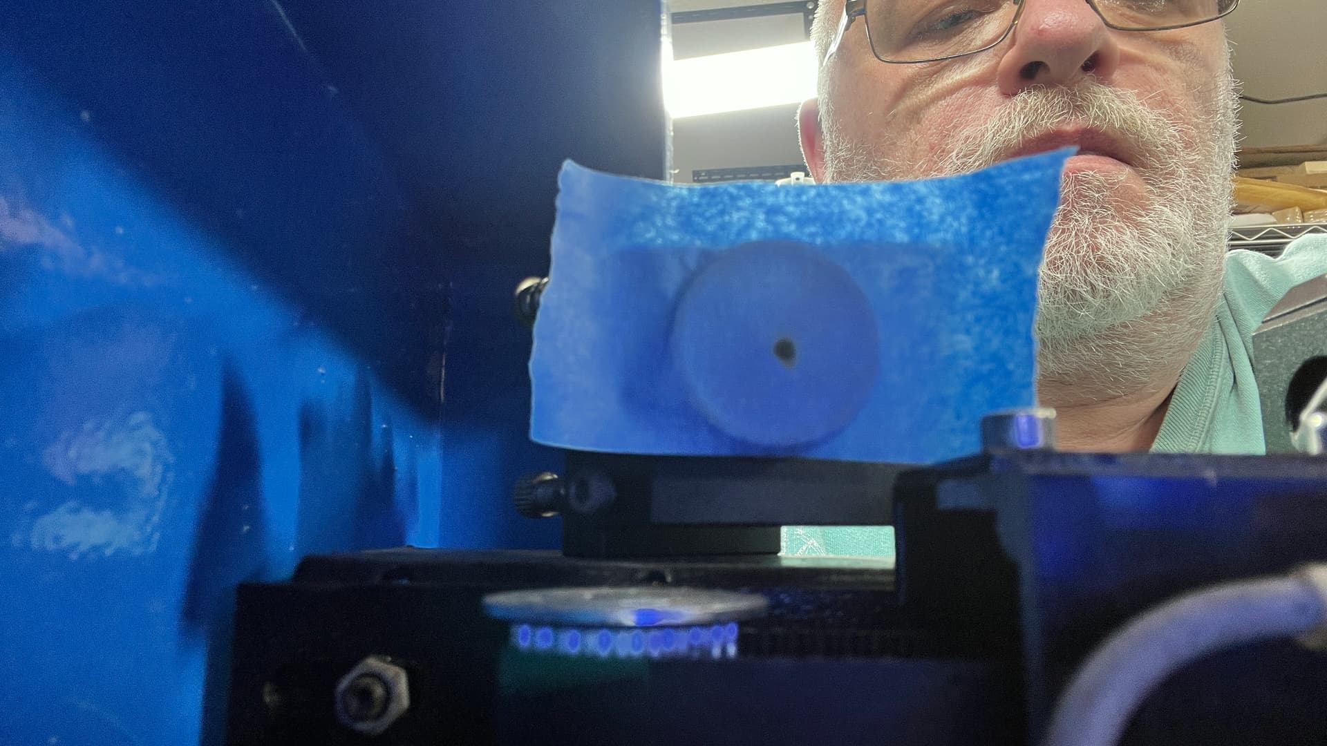
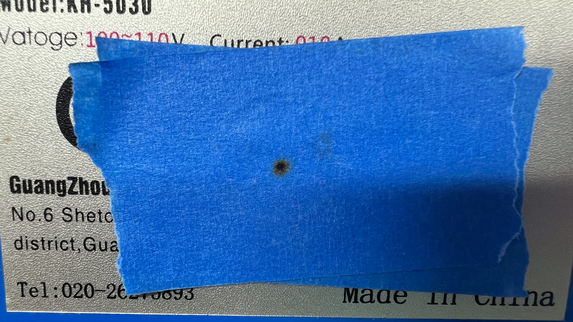
Side B:
Side B shows only the slightest hint of laser burn.
Rocky, 75% and 15 mm/sec is what I use on my 60w to get a clean/burn free cut on 1/8 baltic birch. Leave your max/min at 75 and reduce speed to 10 mm/sec. whether that works or not you should do a material test grid (material test is under the laser tools drop down).
Measure the length of your tube… then see what it’s wattage is likely to be from this chart.
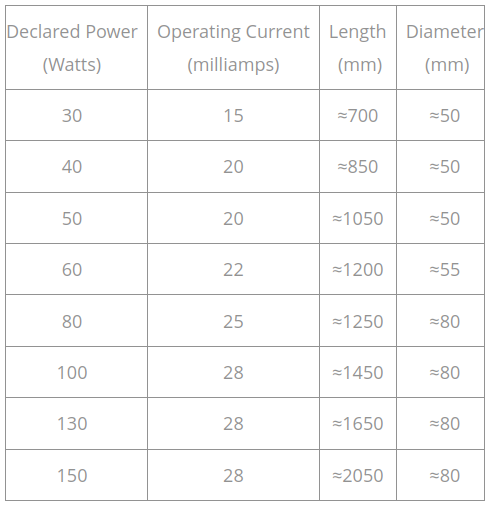
My China Blue 50W had an 880mm tube in it… measured 43W on my Mahoney meter … so much for 50W… This seems common, sell you a 50W, that’s 40W… The K40’s are sold as 40W and the tube lengths are about 700mm, more like 30W … ![]()
It’s unlikely that a 50W tube of 1000mm (1m) in length could be shoehorned into your machines existing case …
- properly working tube
- clean and aligned optics
- proper focus
If you have these three, they work.
Following your outline, you’ve isolated it to the tube…
However, alignment is sometimes more of an art, the more you do it the better (faster/accurate) you become and you spot anomalies a bit faster. I’d be wealthy if everyone that stated it was perfectly aligned and it wasn’t gave me a nickle ![]() Simple fact: we don’t know what we don’t know.
Simple fact: we don’t know what we don’t know.
I’ve looked at your m1 shots and there isn’t enough detail to make them useful to me.
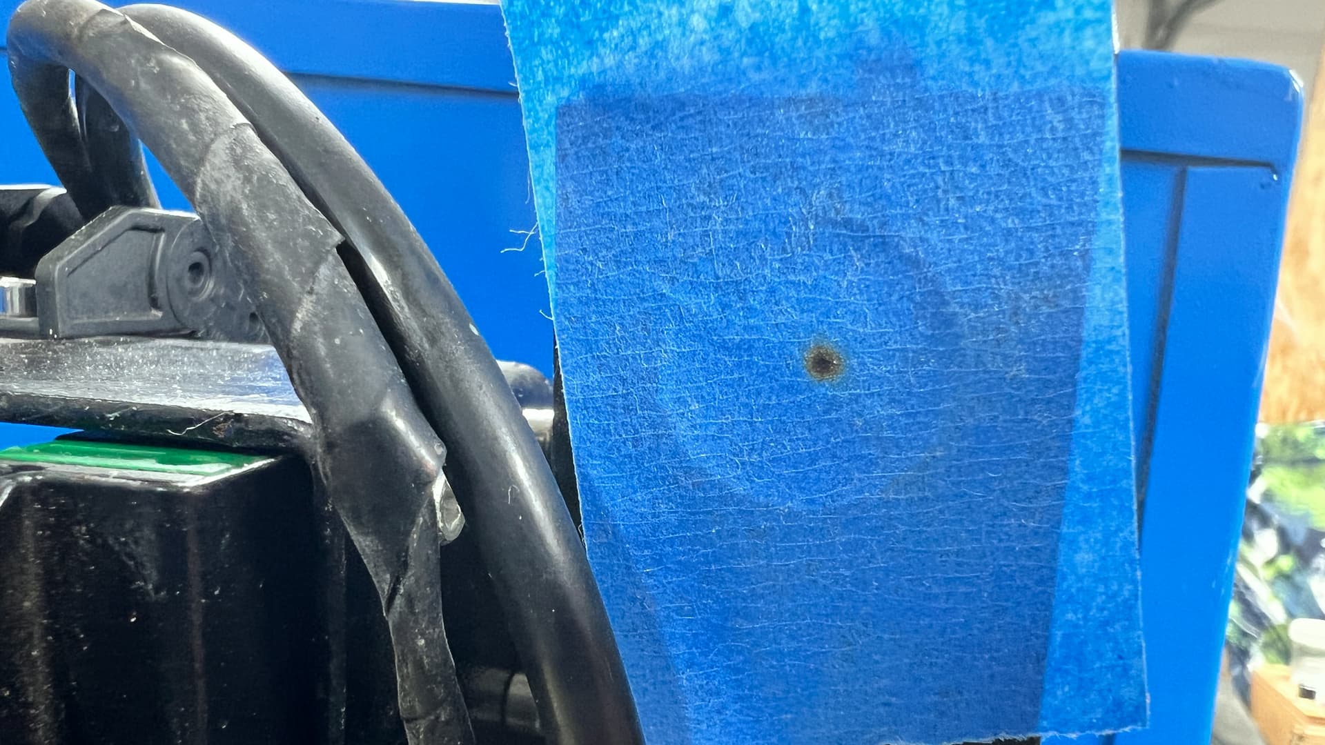
You can set the pulse down to ~10mS or lower, low enough you might not leave a mark. You can pulse it more than once to get the desired burn density…
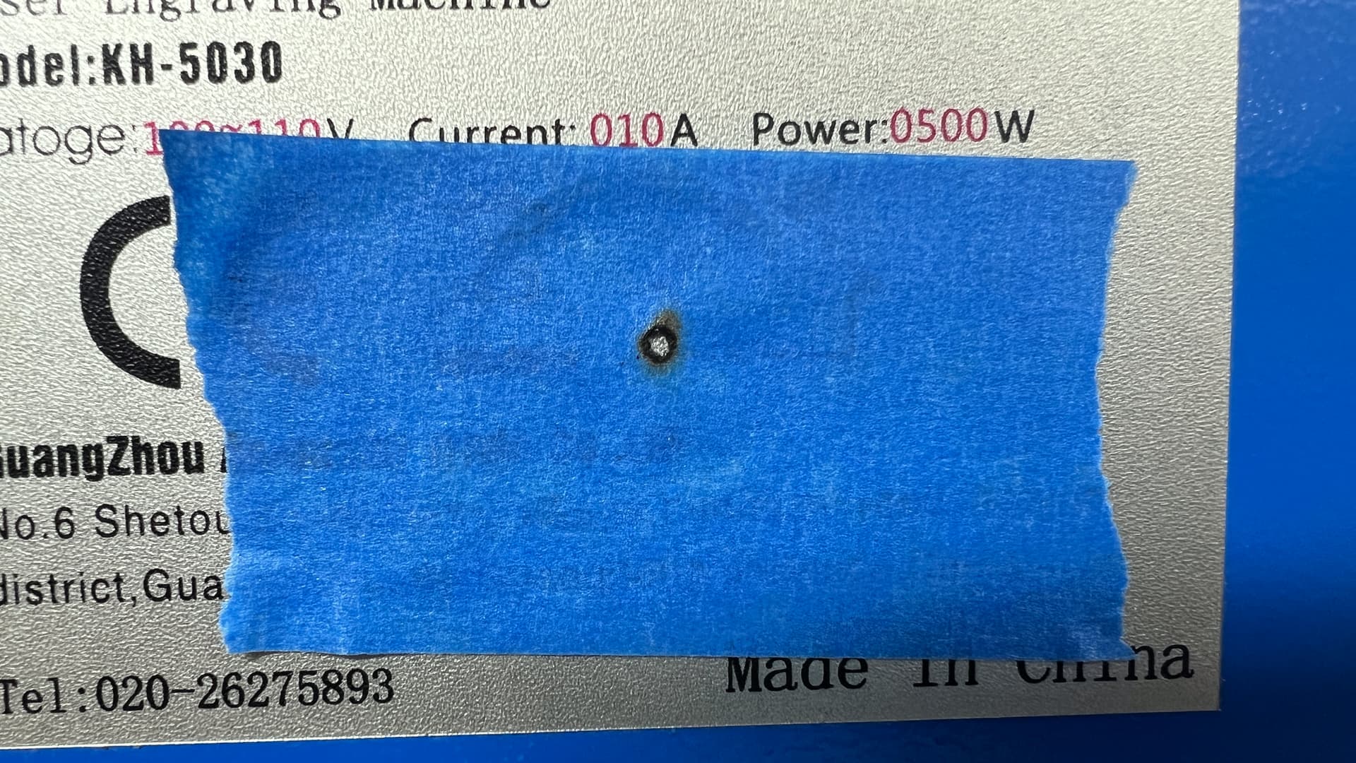
It should show a brown ring to a dark center… It should be round…
The shots of your m1 from the tube are black or vaporized (hole), so I can’t tell what the tube is doing.
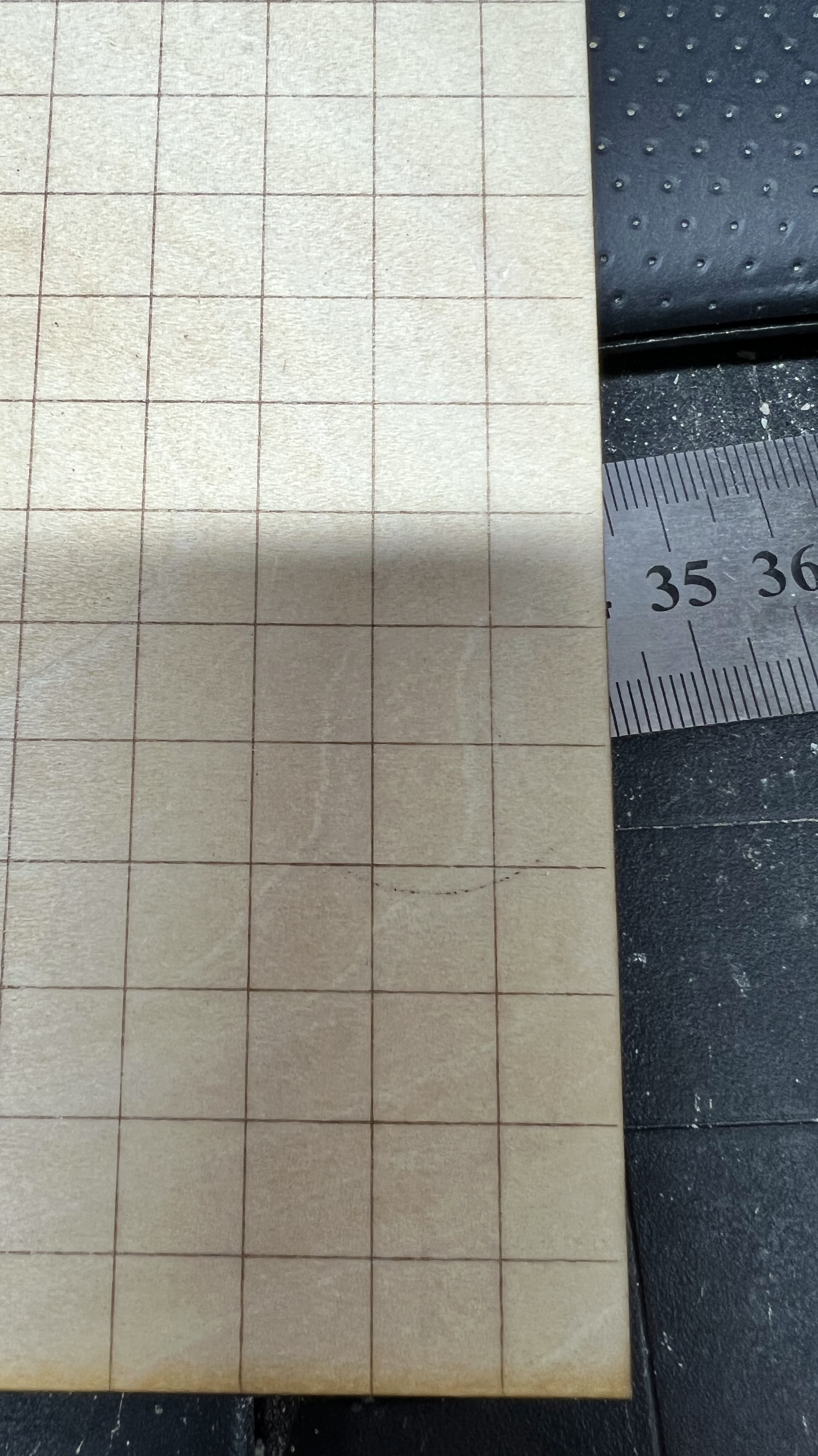
I cut my targets out of watercolor paper… sturdy and are easily marked… they also require no adhesive.
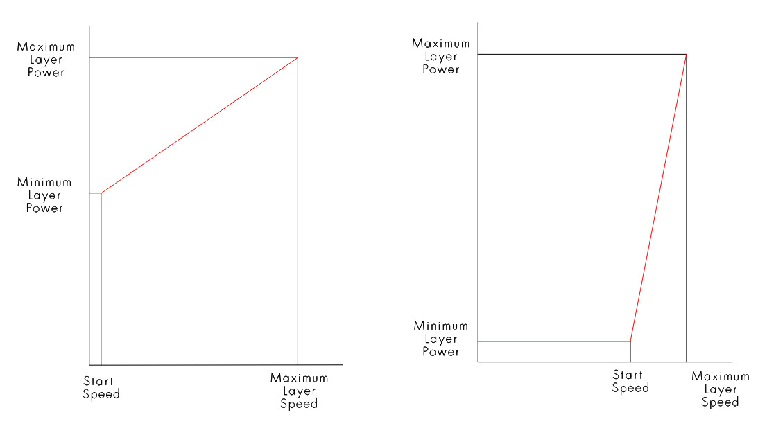
The 10mm/s is actually the start speed value set within the Ruida configuration. My start speed, when received was 20mm/s - it’s now 5mm/s.
If you are running your machine with a vector, at or below the start speed value in the controller, you will only get minimum power… If it’s scanning, there is no reasons to use a min power value.
Power will follow the red line.
I cut 5mm sub flooring at 12mm/s@65% - 2" lens, like in this short video.
Anytime you are trying to fix an existing problem, never run any higher power that absolutely necessary.
The lps has an internal 20 turn pot to set maximum current limit. If you do this, then Lightburn will match exactly percentage power…
If you want to do this, let us know… I can outline the procedure.
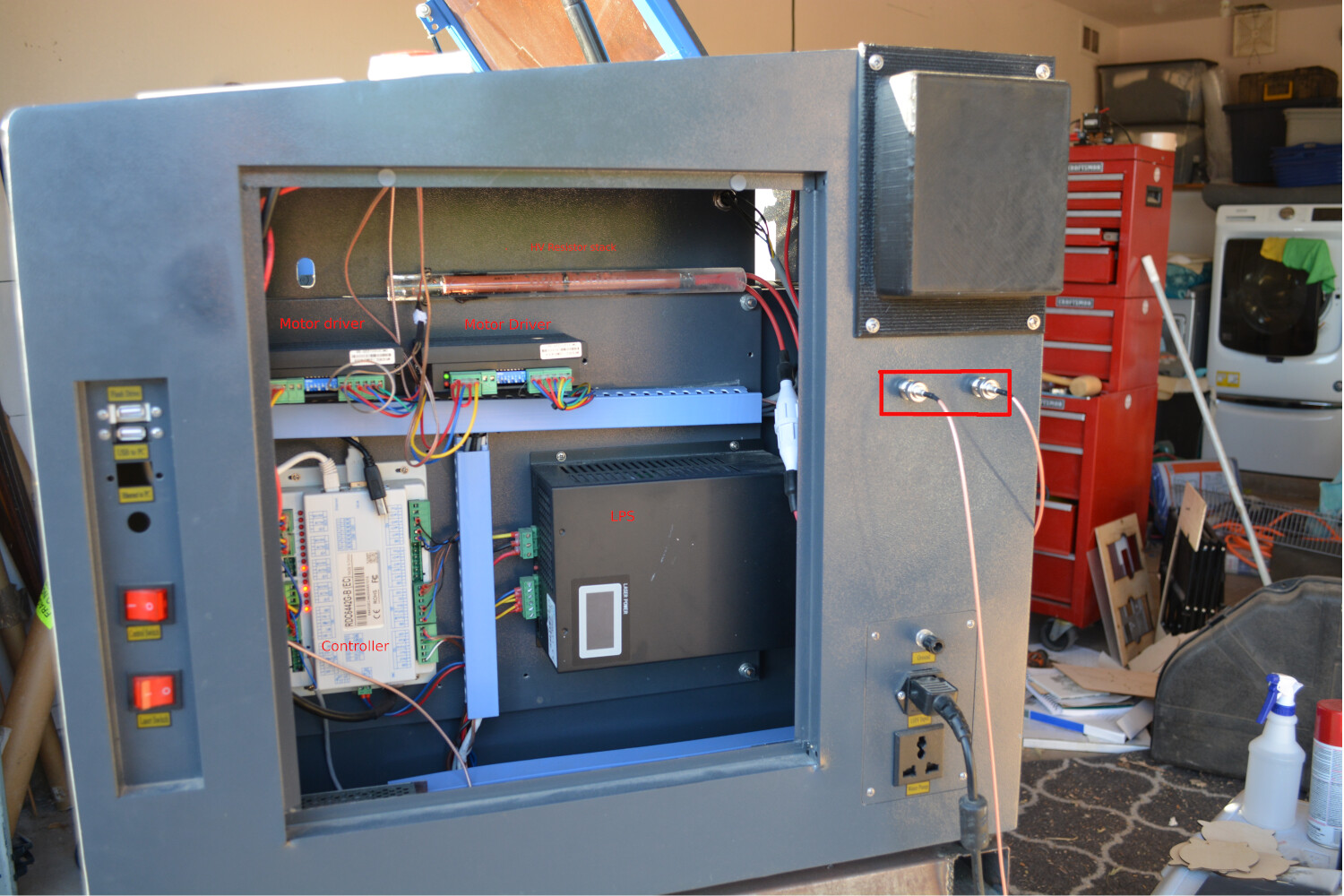
Likely a 6442 type, but you need to open the electronics side of the cabinet to see the controller itself. Controller is the beige box on the bottom left.
Good luck
![]()
Jack,
Thank you for all the info! I’ll reduce the power as you’ve explained and retake photos of mirror one but I have a larger issue at the moment - the blinking light on one (or sometimes both) of my stepper motor drivers has returned (m/n: 2DM542-N).
Also, while the machine is labelled as a 50 watt, I’ve read that in reality it’s probably only 40 watts. Here’s a link to the tube that the previous owner purchased: https://www.amazon.com/gp/product/B07RZ5KY7C/ref=ox_sc_saved_title_9?smid=A3FTM46AEZNI3T&th=1
Based on the chart you show, it’s probably only about 35 watts.
Yes, please. I would like to understand how to do this.
As for the controller, I also believe it’s a 6442G. However, I couldn’t find a label on the unit. Here’s a pic:

Again, thank you for all the help!
I looked at the menu on the controller and loosely followed one of your other threads about setting the speed of the pulse.
Z/U button → Laser Set+ → changed Mode to manual (was set to continuous); then changed Laser to 10ms.
I also changed the Start Speed setting through Lightburn (Edit menu → Machine Settings → Start Speed (mm/s) = 5.000.
Do I also need to change the X and Y start speed?
Is all of this correct?
Also - how does the watercolor paper stay on the mirror frame without adhesion?
The cutout is very slightly larger than the hole… Just poke it in there, so to speak. You can measure the hole on your mirror and cut to size. Might want to cut a circle out and adjust it until it’s snug in the hole.
Start speed determines at what speed it actually starts moving when you’re going to move that axes… after it starts, it’s acceleration is applied as it speeds up. Off hand I don’t remember what my start speeds are set… Next time I fire it up, I’ll look…
Sounds good.
When you load a project it will use whatever values you have picked for that layer. If after it’s loaded and running a job, you change any of the setting via the console, it will be applied as a manual change. So you can change these while the job is running.
Make sense?
Generally speaking, these are pretty tough devices. It’s unlikely that both are bad as they have both gone red on you. I’d check the supply voltage, most of these are driven off the 24V supply…
These motor drivers are about $20 US last time I got one… I keep one around… so swapping them out is a low cost item… still bothers me that both have shown an issue.
The controller looks like a 6442 …
![]()
Yes, thank you.
Any thoughts on why the driver modules are blinking? Or more precisely, how do I find that info?
I found a manual for the module on-line but I’m not sure what it’s telling me…
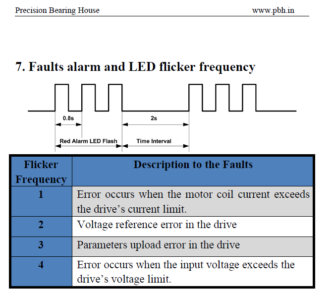
If I’m reading this right, it looks like I’m getting 1 blink. Does that mean the stepper motors are bad?
I’ve never had any of my stepper motor drivers error out… The indications are that it’s drawing too much current, over what is set …
Motor drivers allow you to set the maximum current for the motor.
The switches on the motor driver are used for various setups. You have to look at the placard on the driver (or in the manual) and see what the current limits are for your driver and what motors you have.
These are NEMA motors, a NEMA17 is 1.7" on a side. You’re restricted on what types of files you can upload… these are pdf, so remove the .txt extensions that allow it to be uploaded.
Data-Sheet-Stepper-Motor-Support.pdf.txt (839.0 KB)
This is from the 542 manual I have… is it on for .4 seconds then off for 2 seconds and the cycle repeats?
m545-motor-driver.pdf.txt (307.2 KB)
You can check your switch settings and compare them to the the data sheets… On mine the current limit was set to twice the allowable current for my motors…
It seems odd, you’d be having these kinds of issues from a running machine… makes me suspicious that maybe it’s something else…
![]()
Since I haven’t played with the physical switches, could it be a setting of some type? I don’t think I changed anything but is there something I can check?
If I measured correctly, it looks like my motors are NEMA 23.
Keep in mind, this is a second-hand machine. I haven’t gotten it to run successfully myself, yet.
I’m not an electrical engineer but the best I can tell, the driver modules are set for 3.31A Peak / 2.36A RMS(?). Switches are set at 1 - OFF, 2 - ON, & 3 - OFF.
According to the data sheet you sent, the Mounted Rated Current is 2.2A. That would seem to all be correct, right?
Highly unlikely.
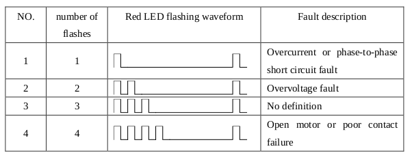
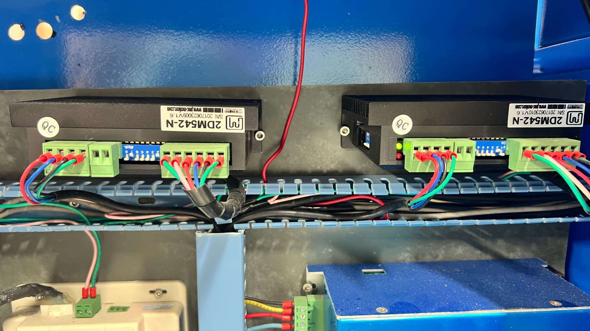
From the original photo, it looks like the switches (Switch block 1, SW1-3) are set OFF ON OFF, which corresponds to 3.3 A based on the only info I could find:
That’s reasonable for NEMA 23 size motors typical of CO₂ lasers.
The error blink patterns seem to vary among various 542-flavored drivers, but having both drivers report an error at the same time suggests a power supply problem, rather than a driver or motor problem.
It may simply be that the wiring from the 24 V power supply to the drivers isn’t quite up to spec or suffers from the usual loose terminals / screws / ferrules.
Your picture of the driver shows the power terminal plug is not connected to anything, which would definitely cause problems. ![]()
Is it doing this?
If the current values are correct, which is likely since it was a running machine. I’d look elsewhere.
I have run a lot with the lps off, so if you just testing the electromechanical parts, don’t power up the lps.
![]()
I’m not sure which plug is the power terminal. Looking at the manual, it looks to me like the empty, two wire connector is for the pulse signal (ENA- & ENA+).
Since I have no background or knowledge in this area, I’m not certain so if I’m wrong, please let me know.
I was standing on my head reading backwards: objection withdrawn!
Yes, that sounds about right. But it’s not consistent. I’ve had times were the Y-axis driver blinks but not the X-axis; other times when both blink; and times when things seem to work properly. But the blinking pattern itself seems to be consistent.
Ideas on where to start searching? Vendor settings?
Good… that’s what I’ve been doing. I’ve tried to get in the habit of not turning on the tube until I’m ready to fire it.
Lol… been there… took me a while to figure out the diagrams, too.
Ok… after poking around a bit more and hours of frustration, I believe I’ve found the problem. I’m going to mark this as the solution in case anyone else is reading this. If after making this repair/replacement, things still don’t work I’ll open a new thread.
While I was hesitant to start disassembling parts I know little about, I finally removed the mirrors. I had tried cleaning them through the openings but didn’t get any better results. Upon removing the first mirror (M3), it became obvious why the laser wasn’t cutting properly - they were filthy and possibly damaged. I’ve ordered a replacement set on-line and am just waiting for them to arrive. Here’s a pix of what they looked like. Keep in mind this was AFTER cleaning them while on the machine.

Thank you, everyone, for all of the help!
2 Likes
Never run you machine 100% or even 75%
You will damage the tube