Coherent RF Laser source signal Line is RJ45
How can I conneting Ruida board?
Image is coherent signal
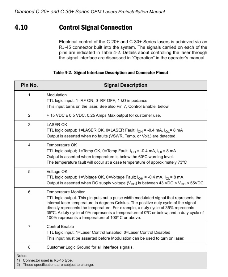
image is ruida rf signal
Coherent RF Laser source signal Line is RJ45
How can I conneting Ruida board?
Image is coherent signal
image is ruida rf signal
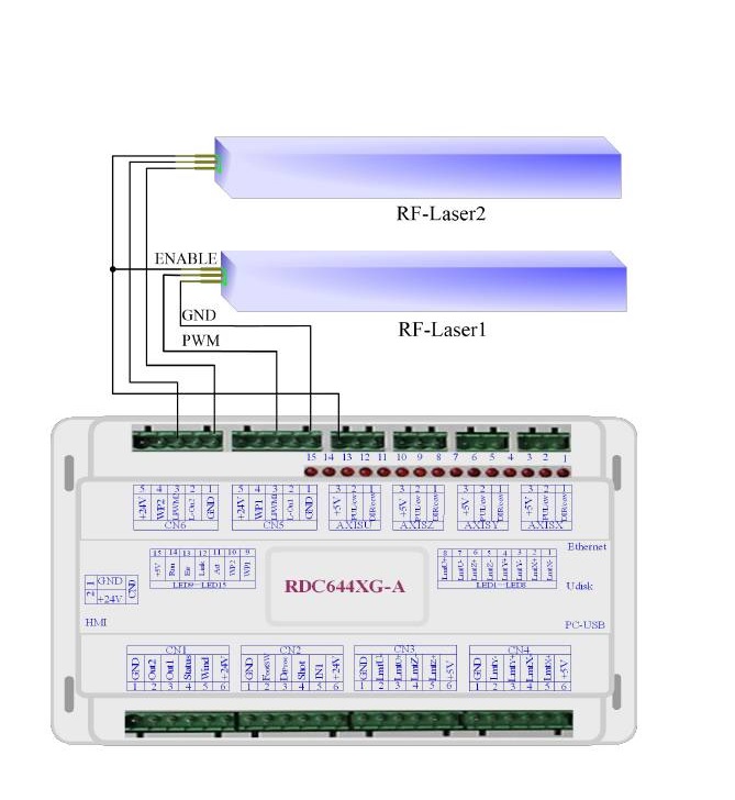
I don’t know what kind of laser this is, but I’ve gone down the RF laser type because of your graphic. I’d think it’d hook up like an RF laser.
The diagram shows the enable (pin 7) wired to 5V to enable the laser.
PWM goes to Pin 1 and is the modulation or power control.
Ground is just a common ground referenced to signals.
Make sense?
![]()
coherent RF Laser source signal Line is RJ45
How can I conneting Ruida board?
Thank you for your answer.
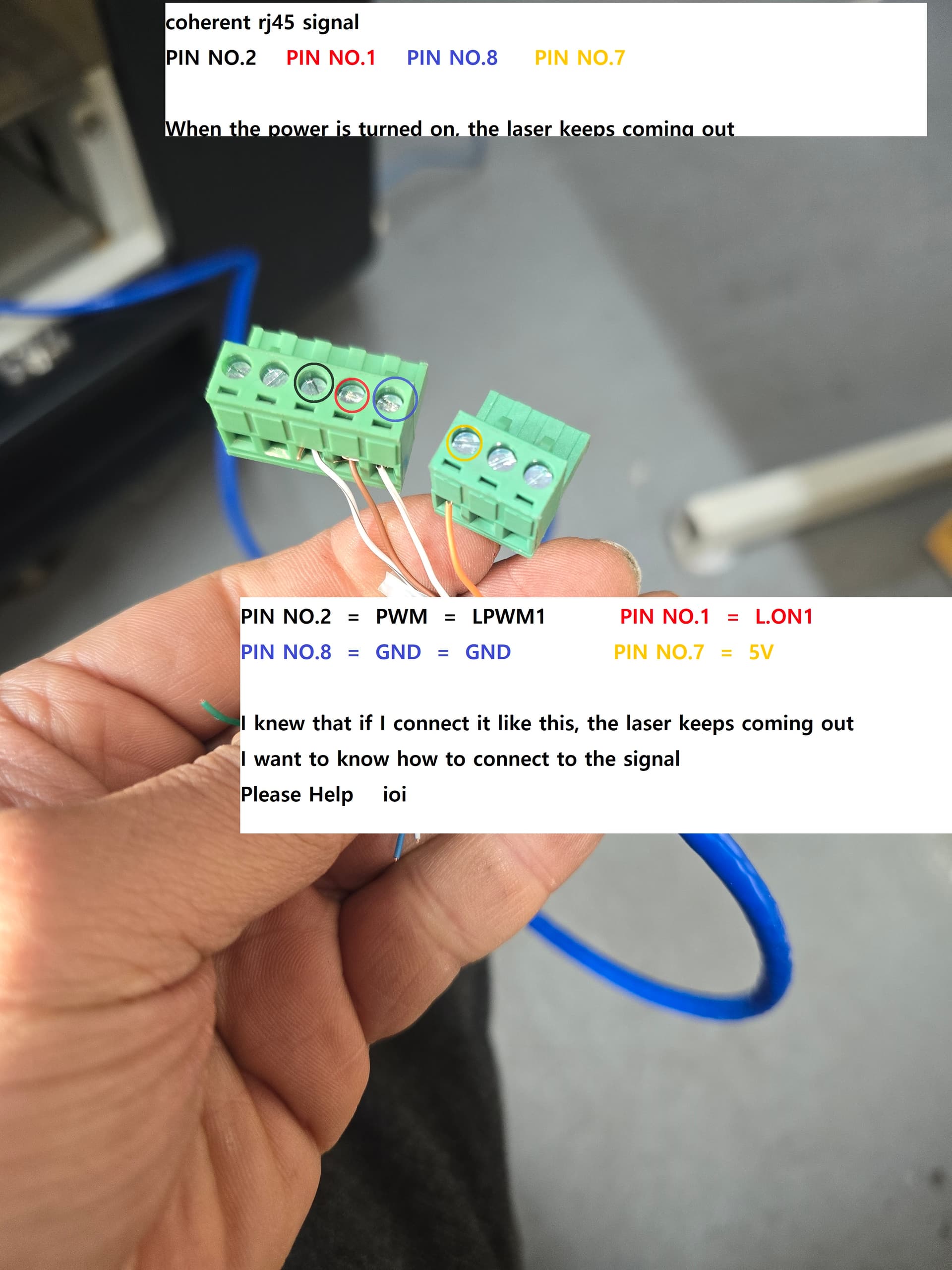
Connect number 7 to enable
Connect No. 1 to PWM
Connect number 8 to Ground
Should I do it like this?
This would be just wired to a 5V source.
RF only uses pwm, that’s it’s only control lines used by the Ruida.
![]()
Not an answer but I was wondering if the pinout configuration is the same for epilog tubes? I was told pin 7 is pwm 5v dc+ and pin 8 is gnd.
Can anyone confirm?
I’m not sure what you want.
Can we see a photo of the laser source? The pin out and wiring you reference here are for a glass tube co2, not an rf model.
![]()
Just a standard RJ45 jack, Epilog RF and Coherent RF tubes look very much alike. So it makes me wonder if they are the same, though I’m pretty sure I’ve seen they have different internal PCB’s.
This topic was automatically closed 30 days after the last reply. New replies are no longer allowed.