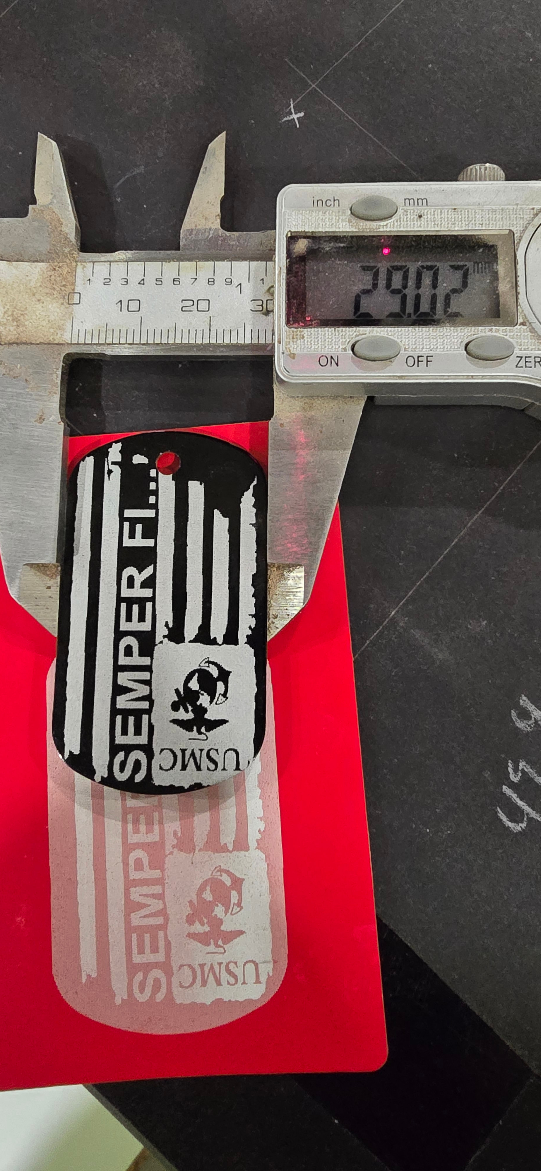
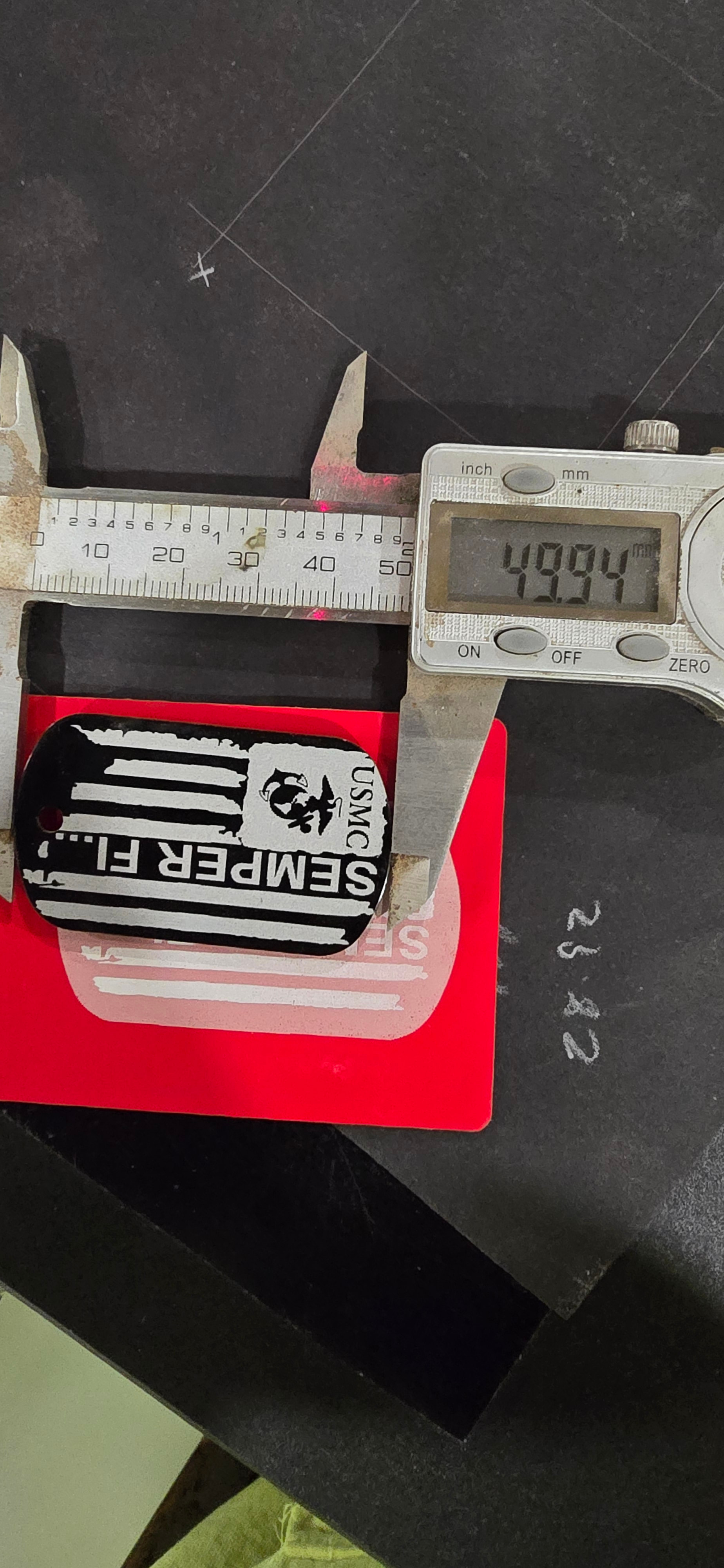
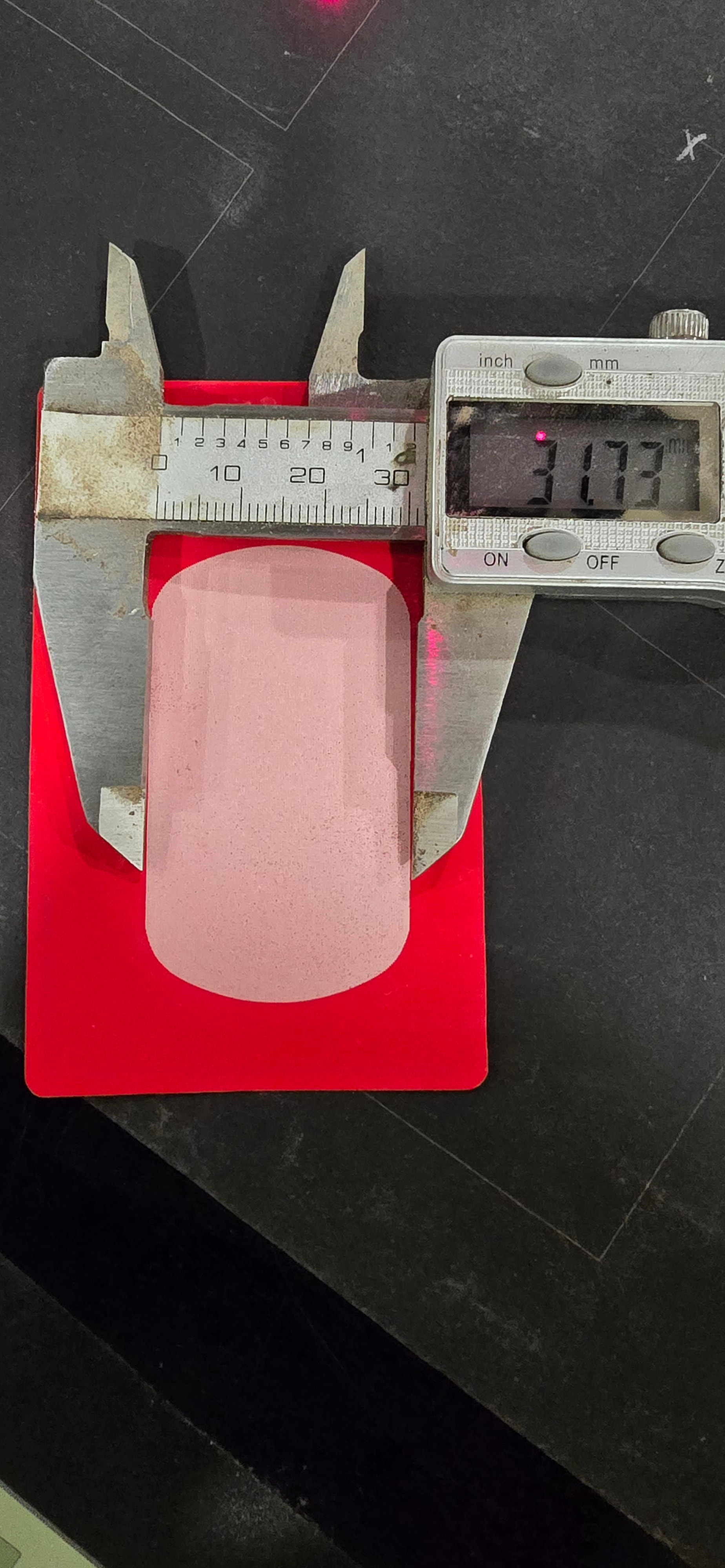
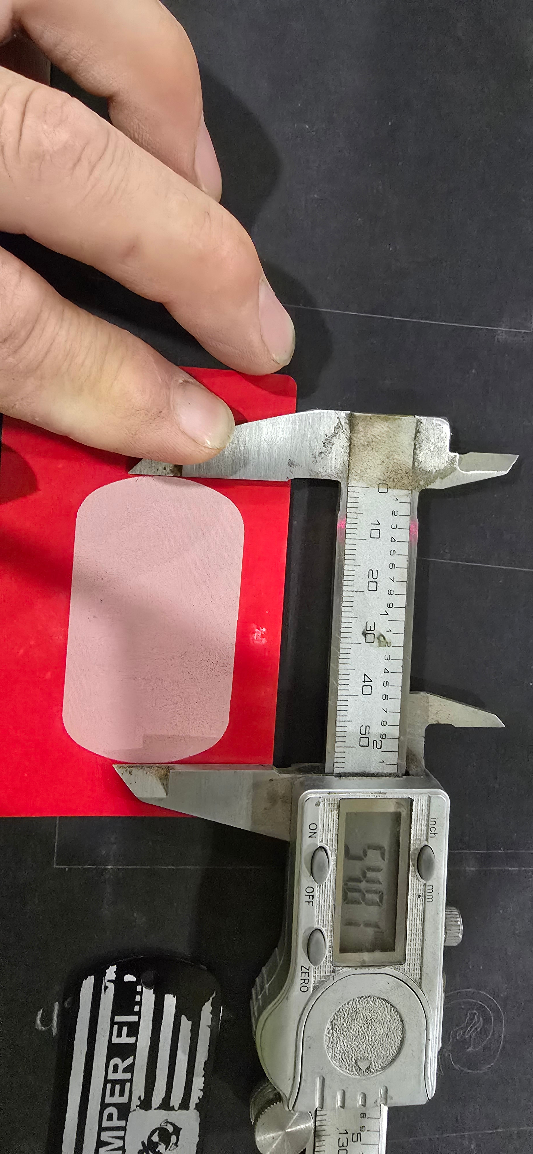
I have done the lens calibration from the video from Lightburn you tube channel and just recently did calibration galvo lens 9 point correction easy, where I tried to get a gnat butt measurement. First problem is when I do a 100mmx100mm square it tells me I have objects outside of the work area when it is perfectly centered but as I am typing this I retried that so I could type the exact message it shows and it didn’t come up, the laser started framing. When I cut the 100mm square it the square comes out to be 110mm. This also happens when I do the dog tags in the pictures, That is how this rabbit hole started. I put the actual size of the dog tag and it came out bigger than it was supposed to. I have something to do for a friend that is expensive to replace and I would like to get this thing dialed in so I don’t have to buy him another if I mess it up. I will attach some screen shots and some pictures please let me know if there is anything else I need to upload. As always I appreciate the help
What lens are you using? Does it cover 70mm square, is it an F70mm or, more likely an F100mm?
Looking at this chart, it shows an F63mm having a coverage of 50mm square. If you want 100x100mm coverage you need about an F150mm that has near this coverage. Last group of number in the part number is it’s focal length.
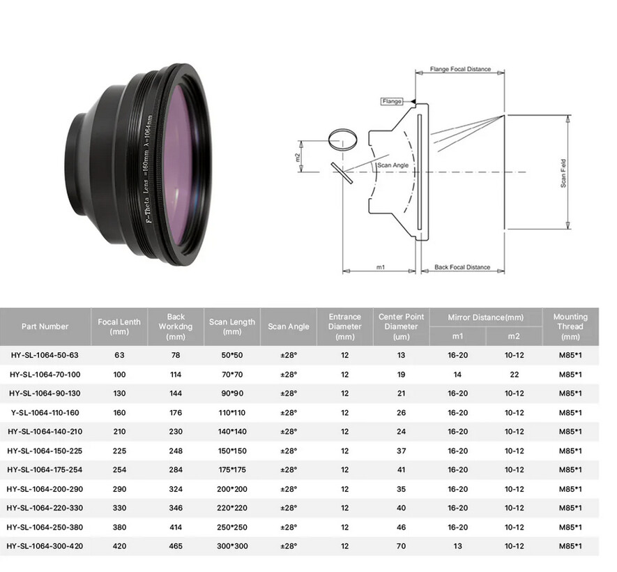
If your machine is capable of only 70x70mm, you’re not going to be able to do a 100x100mm area.
![]()
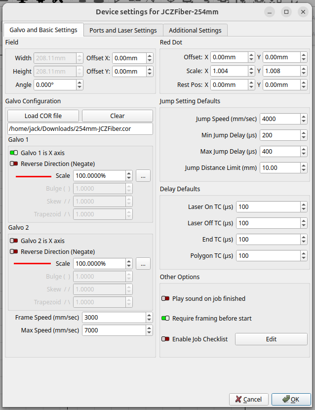
This what it says on the lens F-theta lens f= 163mm ^=1064nm sf:110*110.
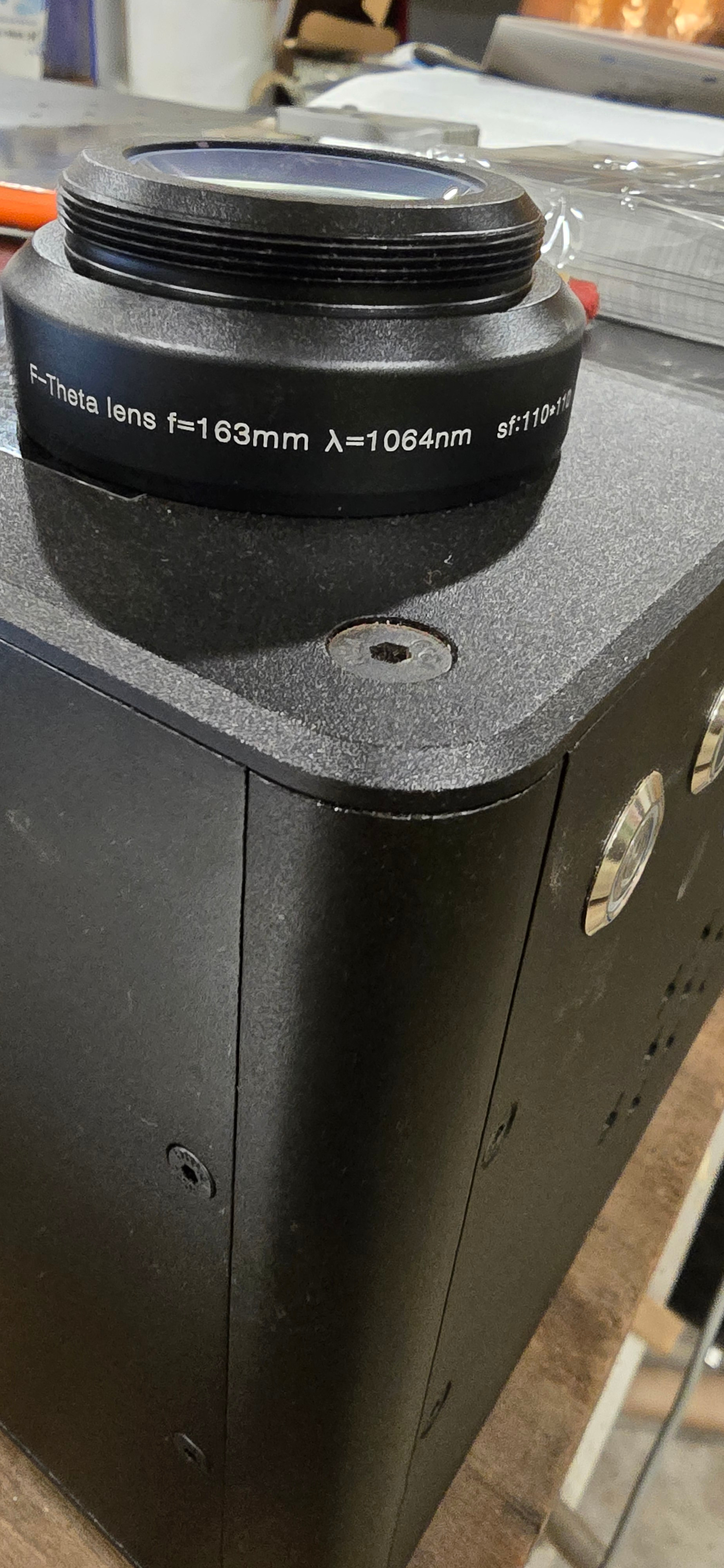
I was trying to achieve the 100mmx100mm because that is what the manufacture said that is this lens working area, I have another lens that comarker say it will do a 200mmx200mm but I haven messed with that one much other than to calibrate it. I am new to the fiber side of lasers.
With that lens you should be able to do 100x100mm. You will be within 10% of the maximum, not sure how that would affect the image. Sometimes when you get near the maximum you have less than stellar results.
Did you import the configuration file from the vendor when you created it? I assume you did. There should be a different one for each lens.
![]()
I did import the file for both lenses and then went through the calibration process on the video because a square wasn’t a square, it had bends and bows to it. I got that dialed in pretty close. I do the aluminum business cards and recently found these dog tags, (typically GC’s superintendents and contractors on job sites don’t just throw them on the ground after they read them yes that happens, it is a rude, cut throat world out here in the trades Lol) I don’t run the file as a image (I haven’t figured out how to cross hatch on a image yet and I get a cleaner finished product with the cross hatch) and the other side is simple text, I didn’t want to upload that side because it has my email and phone number on it and I get more than enough spam calls and emails as it is
My real question was, why is the laser burning bigger than the value I put in, when I was typing the title I was trying to get all relevant information of the laser in and was supposed to put my biggest concern but the dog distracted me and I probably got 5 phone calls and some how skipped right to the description and forgot to circle back to finish the title of the thread. When you (Jack )replied I saw that I messed that part up. I am not real concerned if I get less than a 100mm let’s call that a problem for another day lol. For now can anyone tell me why the laser is burning bigger than what I put in?
The machine knows how much area you have by your lens selection. Any way you could have mixed up the markcfg7 files between your lenses?
So far, I can’t think of one this occurred and it was traced back to the wrong configuration file for the lens. I remember you saying you used the lens alignment facility in Lightburn?
There is also scaling that can be applied. Maybe @Albroswift can assist, I’ve pretty much run out of ideas… ![]()
Give him a chance to respond, he’s dealt with a number of similar issues.
Hang in there.
![]()
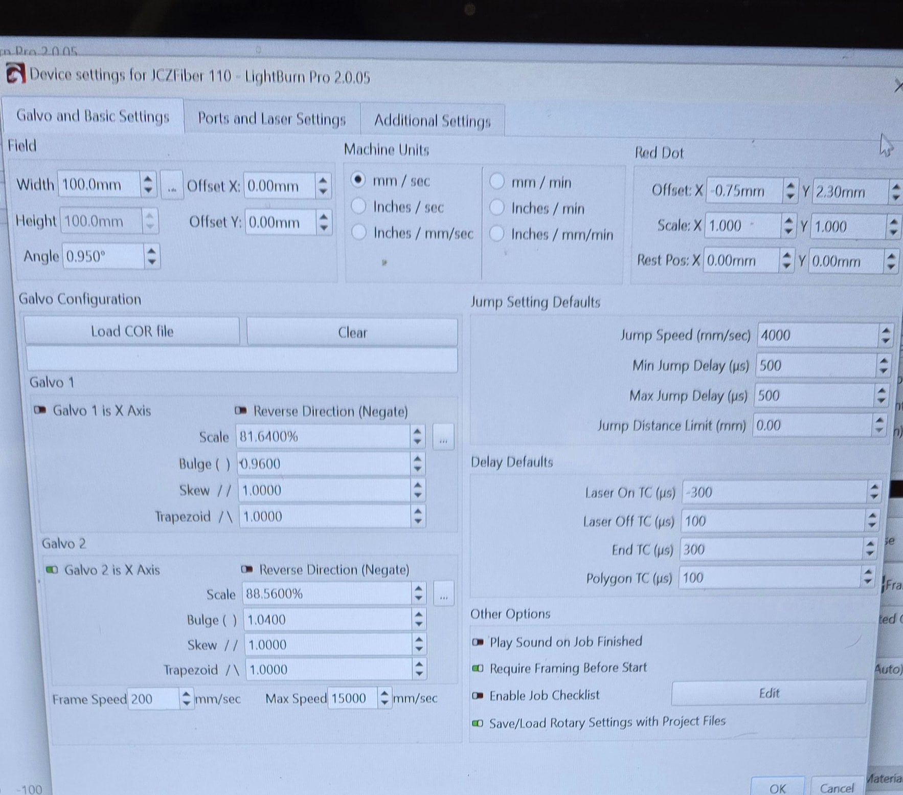
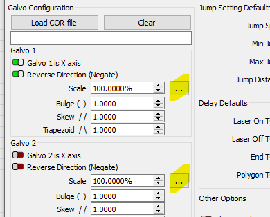
There was some scaling applied to get rid of the bows in the square, I wonder if I need to apply the same sc
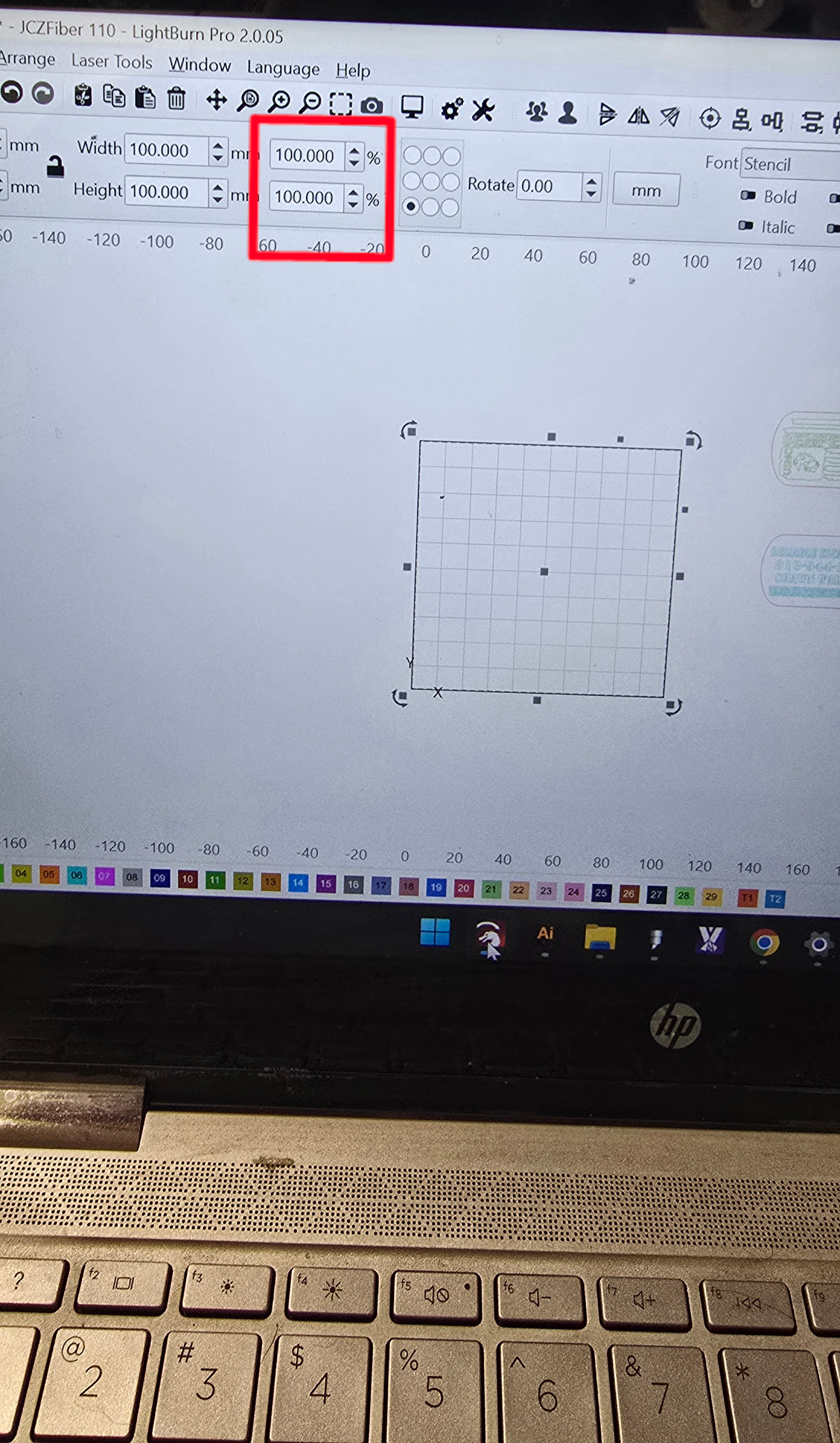
ale to the the box in this picture, I don’t know enough about this stuff, but I could try that when I get home from work hopefully there is a more permanent solution so I don’t have to go in a nd change that everytime
Having the same problem but with factory 11-x110mm lens. My circle should be 38mm and coming out 44.7mm when i burn it. Not sure what i need to do? Ran calibration for galvo lens in lightburn, problem still there.
Couple quick questions, been following along but might have missed:
After the 9 point correction did you run the scale utility?
It looks like the lens is F163, not 63 Also if the lens says 110x110, that is the working area for sure, regardless of what the manufacturer says. Is that what you entered into the set-up?
At the end of the setup you can maximize area which will give you a little more, basically it circles the square.
Do you have a procedure to assure you are in focus every time? (Focus stick, chain, etc)?
Like I said I might have missed it but I think you need to run 9 point, then run scale.
The 4th picture in my initial post is what ended up with after following the procedure in this video https://www.youtube.com/watch?v=x08cRPkyToc&list=PLwL4iB6JZSDzjF11U_DSOaxYsIeLp3-f3&index=11
My focus measure point is 201 mm the laser has the 3 beams that become 1 and I double check with the ruler that came with the machine but it is always on the money.
I did the 9 point but I don’t recall anything about scale but it did change the scale in the 4th picture from what is was after doing the steps in the video but I really was going for close enough, but after I noticed that things were not coming out the correct size I reran the 9 point and was really trying to get it as close as possible
After running 9 point engrave a square and measure. Enter the result and desired size 3 dots is the scale utility. Fix you right up I bet.
Focusing is really important, check it by raising/ lowering while continuously firing and listen for the loudest burn. adjust your red dots to that point. Problem is when you change lenses the red dots are way off. Cut a stick for each lens. Then set scale. Never trust factory.
Here is the documentation. Scroll down to “Calibrate Axis”
I have four lenses, so I gave up messing with the pair of focus diodes and have them turned off.
They are difficult to setup and, most are too bright for accurate adjustment, at least for me.
I followed Laser Everything video on setup a new fiber.. they show a T shaped tool.. These are a couple of mine.
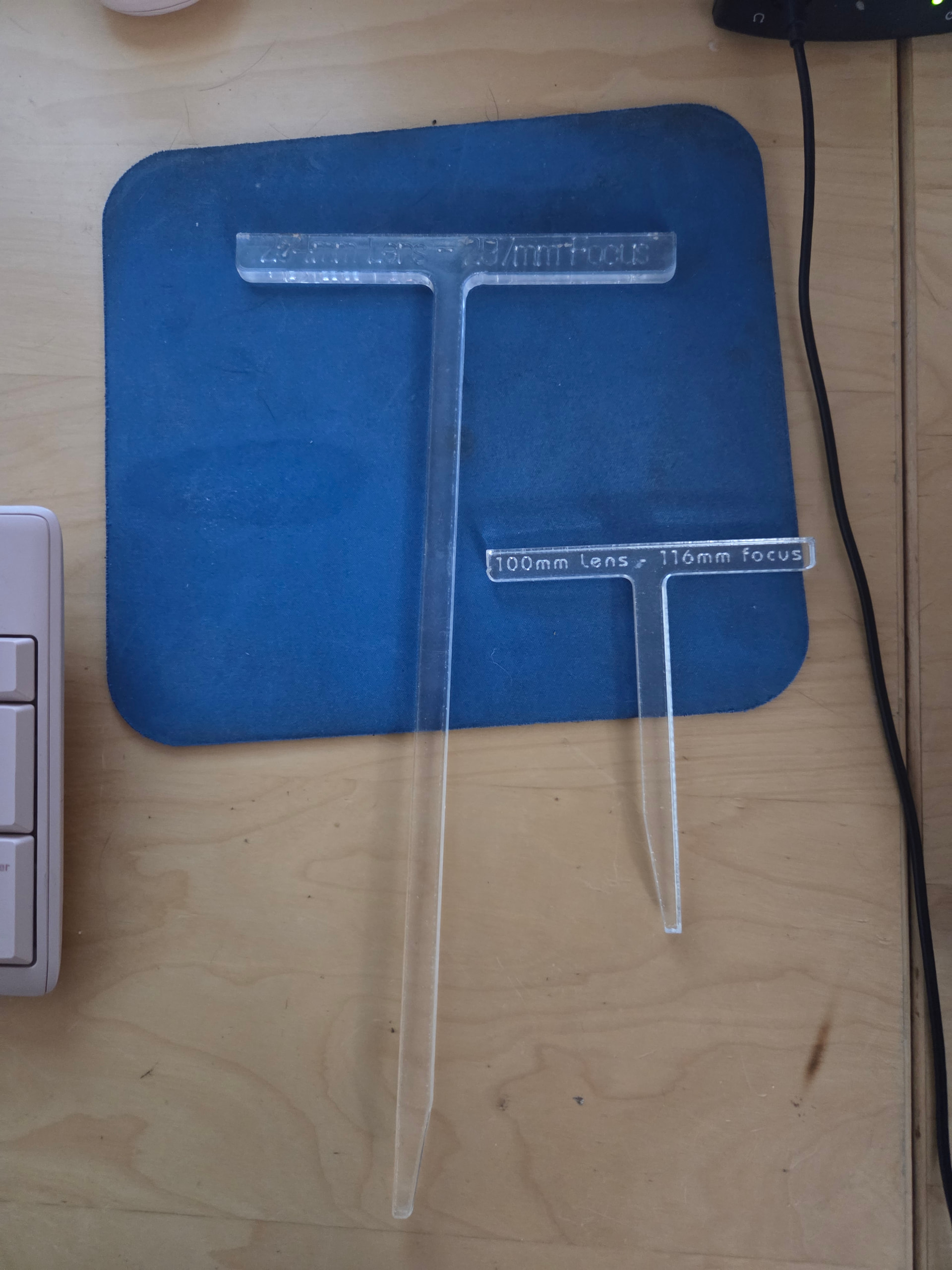
I would follow @Albroswift suggestion, focus it yourself.
![]()
I started with the focusing lasers but with 3 lenses wast of time like you say, and even when dialed in didn’t seem very accurate. Then went to focusing sticks, way better, industry standard. Then to DRO, now CNC.
CNC is the bee’s knees! Select lens and enter material thickness, wait for the whirring to stop, mark.
I only have the 2 lenses and don’t use the other at least not yet, if I get more or start swapping them out I will 3D print some sticks. I am really only messing with the dog tags and business cards at the moment also some mirror cases like a make up compact. I put company information on them and hand them out as business cards, The compacts, I give to the Directional drill guys I do work with it is the best way to look down in a deep trench where you flashlight on your phone won’t reach. You reflect the sun down in to the hole
I ran the 9 point and solved the problem with the requested size vs measured size, I didn’t go in to that little box the last time I did it and I am not sure if I did it as a part of the process in the video. Thank you for all your help on this