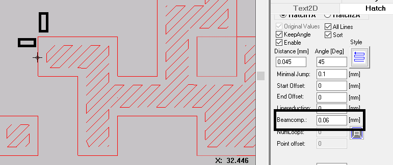
is there an option to compensate the laser beam width? I have the problem when i laser a small font it looks a little thicker than i designed it. I have this example here from my work, there you can define a small gap between the area and the outline. In this case .06mm
Can you include some screenshots of the file you are engraving, and a photo of the results you are getting including the type of laser cutter/engraver you are using and all the speeds and power etc from your fill?
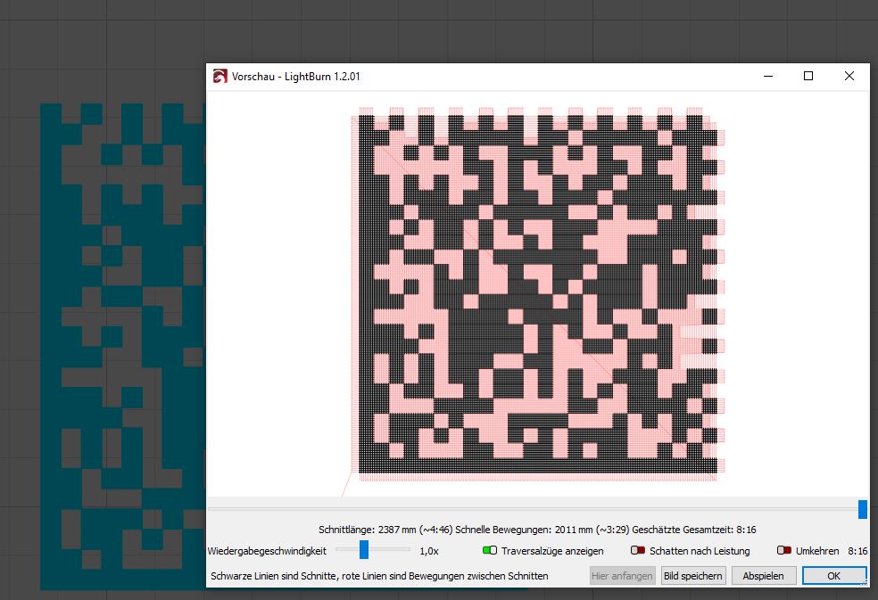
Of course, i can do it later. Best example is a Datamatrix-Code: you will always have larger filled rectangles than unfilled rectangles if you go with your laser to the outline-edge.
What are you working with? A diode? A Galvo laser? A CO2 DSP laser cutter? What sort of setup do you have. You are still leaving a lot of information out, or perhaps I have missed something? Please be a bit more detailed about what you are working with.
Hi, it´s a brand new Sculpfun S10, Diode.
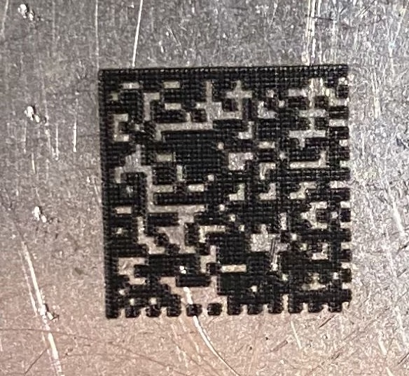
I just lasered a DMC on Metal, and you see that the black regions are thicker than the “non black” regions. On my work we make use of this “compensate laser beam” function, to reduce the thickness.
Anyway, you can read the code without problems, i just wanted to know if there is such a function that i can use. Sorry for the quality but i have no microscope.
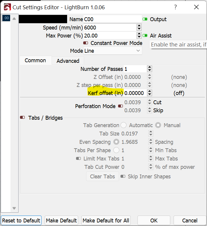
The closest thing to this is “dot width correction” but is only available for Image layers. I think the primary intent of the tool is to account for over darkening of areas due to beam width. I’m not certain but this might work for your purpose if you convert the vector data matrix to a raster image.
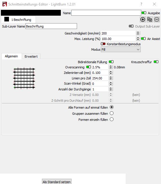
First, you can try to lower the line width (Zeilenintervall) to 0.08mm (318DPI) which is the native resolution of the S10 laser beam. Test again, and then we can check if there are other compensation methods.
That should really only account for overlap within the fill area. It shouldn’t account for burn outside the fill area which is what I believe the original post is about. Only beam width would account for that.
correct, i´ll try it later that day, but if you laser a 1.5x1.5mm rectangle then the output will be at minimum 1.58 x 1.58mm + the individual annealing color gradient.
That could be the case. I wasn’t looking at that angle of it… just that the original premise of the actual filled areas intruding on the unfilled area.
How are you doing this? Is this on stainless steel?