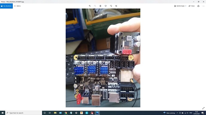
Hi all. I have a MKS DLC32 v2.1 and I am trying to get it working with my laser engraver (3018 with cheap Chinese laser module. I have installed all firmware correctly I believe. I have managed to get the stepper motors moving but not the laser powered on. I am new to this and I have not found a clear answer to this problem on any forum how do I connect the laser to the control board? Thanks.
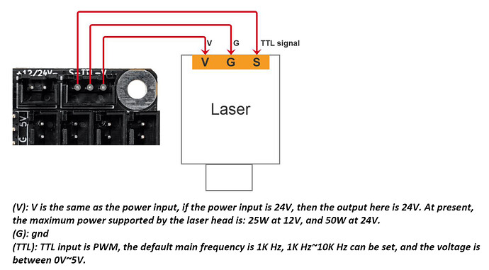
This is from the DLC32 wiring manual:
In your case it should go like this from controller → laser module:
Left Pin->PWM
Center Pin->G
Right Pin->12V
A few things that need to be true for this to work.
- Is your power supply a 12V supply or 24V? If 12V you can connect to laser module this way. If 24V you’ll need to exclude the 12V wire and supply separate 12V power to the laser module, either a separate power supply or a step-down converter
- Apparently the DLC32 is only rated to ~2A (25W at 12V) for the laser module through this connector. If your module is higher then again, you’ll need to supply power separately.
Thank you for your help it has worked. I should have been able to figure that out myself but my head is up my arse and I have already blown one board with the power of pure ignorance. Will the board be sufficient for the sculpfun s9?
https://www.amazon.co.uk/gp/product/B09ND67J9X/ref=ppx_yo_dt_b_asin_title_o09_s00?ie=UTF8&psc=1
No. Sculpfun S9 claims 12V 3A for max input. That’s too much for the controller according to specs. You’d want to provide a separate 12V power supply in that case.
Could you recommend a 12v power supply and show me how I would wire it all up? Sorry I am relatively new to this.
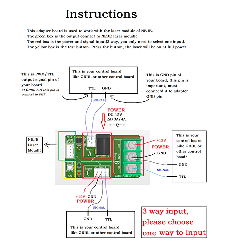
Probably easiest to get an adapter board like what Neje offer. It can be bought separately or with one of their modules. Atomstack M50 modules come with an adapter board. I haven’t seen Sculpfun offer an adapter board but wouldn’t surprise me if they did.
The diagram might be a little confusing at first but it’s relatively straightforward once you understand what this does. It’s meant to take PWM/TTL signal and power from 3 different types of connectors (A, B, or C) and adapts it to a connector for the laser module. From what I know there’s no intelligence in the conversion. It’s really just a physical adapter. I suspect the common pins on each of the input connectors are all joined in fact.
So in your case, you’d need to provide 12V to the connector either in A or B, not C since that’s what we’re trying to avoid from the DLC32.
What is your power source for the DLC32? If you’re using a 12V supply with open terminal then probably easiest to just piggy back on that and supply power through to the B connector. You could connect your PWM/TTL and GND signals from the controller to B as well. I suspect you can mix power signal on one connector and TTL on another if you want to use connectors. So you could get TTL and GND from your controller to the A connector using a 3-pin to 2-pin cable… or use a 3-pin to 3-pin into C and remove the power wire for power.
If you need a separate power you just need one that’s center negative and rated to at least 3A. I’d suggest going for 4A+ for some headroom. Not sure about the specific size of the barrel.
On the output side of the board the connectors are not listed but it’s 12V, GND, PWM/TTL, and Temp sensor going top-down. You can ignore the temp sensor pin.
This topic was automatically closed 30 days after the last reply. New replies are no longer allowed.


