"connecting to controller" fail - is there a listed boot sequence for Ruida firmware? [solved- see last posts]

Is there a list of what steps the firmware takes, when the Ruida CPU boots up?
Like homing, then once ok, check for water flow, then once ok, move to origin… or whatever is the actual normal sequence of checks in booting?

And which lights on the controller should be lit when in operation?

I was in the middle of a job - just finished 10 minutes of engraving Rowmark/traffolyte, and it went to cut the perimeter full depth.
It did the X axis cut, and then instead of doing the Y next, the display flickered, and it rebooted.
It asked me if I wanted it to restart from the error/stop, but it flickered and rebooted again, then tried to home itself, then travelled back, but failed, and rebooted again.

It does home properly - then gives me a ‘fail to connect to controller’ message. This is regardless of whether the PC is on or not.
(It doesn’t actually say ‘fail’ it says ‘connecting to controller’ which it fails to achieve.)

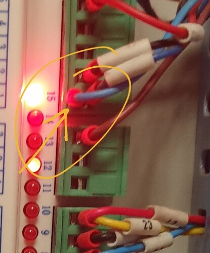
The red #15 LED on the RD6442S (or G?) controller is lit up. (means +5vDC… but I’m not sure what it means - error, or happy?)

I had a spare Rd6442S controller so put that in - no different. I checked the PSU - it puts out 24v DC which is ok.
I have not tried to replace the RD keypad/console yet… perhaps I ought to.

It gives me ‘fail to connect to controller’ messages, but ‘what’ is failing to connect to the controller?
Then continual attempts to reboot, with the console screen going off/out, briefly.

Any thoughts would be appreciated on how to fix the issue, or work out what the cause is!

If I can upload a 20 second MP4 video I will- it might take a while to upload though.

http://www.gattonheavyhorses.com.au/…927_155906.mp4

Best wishes,
I don’t think there is much about how the Ruida really work inside, especially at that level. Most of us know what we can see it do and only guess at what it’s really doing…

But the message sounds like the console is having a problem talking to the controller. I would get in there and unplug the console at the Ruida and return it making sure it’s seated properly.

I don’t know if the console itself is hardwired or another connector for the cable.


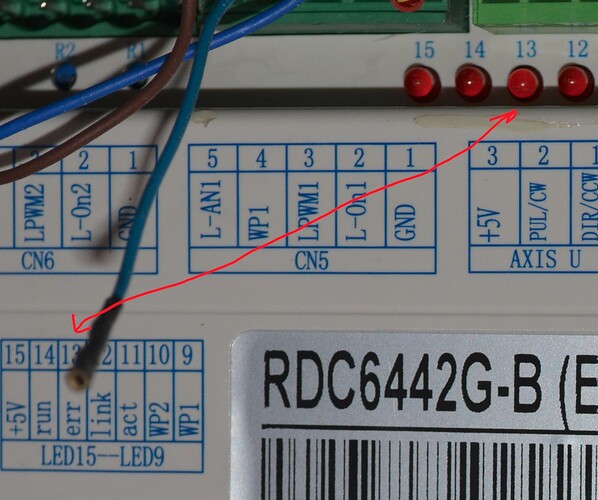
On the controller itself are banks of led indicators. It is normal for 15 (5V) to be on. 14 seems to just pulse at a rather slow rate.

If 13 is on that a hardware problem with the controller. :face_vomiting:

Link is on when there is a hardware connection via Ethernet. Link does not indicate you are ‘talking’ to it, just that the hardware is recognized.

At the other end of the Ruida is the home/limit switch inputs…

:smile_cat:

Thanks, Jack. I’ll see if I can swap out the keypad/console, with the spare one.
I guess the HMI plug at the top, beside the 24vDC input, might stand for ‘Human Manual Interface’, perhaps that’s it!

I was unsure if LED #15 being on was good, or an error signal.

15 is fine… it’s the ‘err’ one you don’t want…

Good luck

:smile_cat:

Thanks Jack.
Update:

  1. I changed the display console, swapping with a spare I had. No different.

  2. I connected in a spare unused/new RDC6442 controller I had. No difference in bootup or message.

  3. I put in a new 24v DC PSU for the controller. No change.

It’s like something is starving the controller & console for power once the steppers get going beyond about 5 seconds travel.

  1. I bypassed the mains power EMI filter, in case one of them is the culprit. No difference.

The 2 PSUs that supply the X & Y drives are putting out the correct voltage.

I tried disconnecting the power leads to the drives - no difference except it can’t home.

When it fails and beeps, LED #12 (Link) flashes faintly.
I’m not sure what that means is linked between what - and whether good, or bad.
1 & 3 are sometimes on - but that’s only indicating that it homed at X & Y limits, back right corner.

Had to think about this…

Does the machine ‘stop’ when you press ‘esc’ on the control panel? Can you connect then?


If it just keeps rebooting, I’d recommend that you isolate the controller and see if the issue changes. You can unplug the motor drivers and anything else, such as the lps. Only need the power for all practical purposes.

When you power it up, keep pressing ‘esc’ until it recognizes it, within limits… it should only take a couple of presses…


Does the console have a removable cable, can you change it out?

I would have to conclude that it isn’t talking about a connection to your computer but more of some internal problem connecting to it’s console. Mine boots fine without a computer connected and they will run stand alone.

:smile_cat:

Thanks a lot for the reply, Jack.
The machine homes, now, double-checks its homing, then starts to move to look for the last origin set, and then beeps, the screen blacks, and restarts, ‘connecting to controller’ again, repeat. repeat.
The only lights on the controller are 15 (power ok) and occasionally #12 (network I guess)
The limits are ok.

Pressing Esc a lot made no difference - it had not finished booting and moving to origin to be receptive of other commands.

I’ll try & upload a 45 sec video.

The display console connecting lead is only one-ended. When I swapped in another new display, it was no different.
Ruida boot fail 3

Here’s another 45 second bootup, blackout, screen fail & beep, shwoing the controller LEDs as well.
The PSU green LED does not fluctuate, as far as I can see,

Ruida boot fail #4 - 45 seconds

Hi Jack, I have another update on what fixes don’t work:

I unplugged the Y cable from the Y driver, and started the laser…
The X homed ok, and I was able to quickly press Esc, and use the arrow keys to drive X across the bed, left & right. until the blackout and beep happened. and happened, and happened. etc, as per the videos.

Then I unplugged X and plugged in only Y stepper wires from the drive to Y stepper, and booted up. Halfway down the bed it blacked out, beeped, & went into the usual beep-blackout-repeat mode. I restarted, and same. I turned off and let it start from right back near home, it homed, then I pressed Esc, and could use the keypad keys to drive Y forwards to me about one metre, until it blacked out & beeped. Repeat. Repeat.

This suggests to me it’s like a power/time issue, as if a capacitor is discharging, and then there’s no oomph left to continue the controller’s own internal step wants, till I turn it off and restart. ?

I might try another 24v PSU swap out…

The screen blackout and beep also happens even if both stepper & power leads are disconnected from both drivers - implying it’s independent of the steppers & their 3-phase delivery wires. (suggesting the stopping & blackout is not due to a short in the stepper wires flexing n the plastic cable chain.)

The display cable is single-ended.and can only be changed by changing the whole console. I’ll try that again, too.
Done. No difference.

I’m tempted to put fresh 24v DC wires from the PSU to the controller, and see if that helps.

I decided I wanted to get the user & vendor settings onto the other controller, so if I ever needed to do a direct swap, I’d have fewest issues, in theory.
After reading comments about unplugging everythg, I was game to start it, with just the display and 24v power. I had to assign a static IP address the same as what was on the other one, and did, and it was happy. All lights behaving as expected. I plugged the LAN lead in, and 11 & 12 did the right thing - 12 was on, and 11 flickered whenever data was sent. I had to read the embedded user & vendor settings, (all incorrect defaults) then import old backed up ones, and write - all good. Then I sent a file to the new controller via the LAN. That was ok too.

So I went back to the problem controller on the laser, and unplugged all plugs. The Bootup was textbook perfect, but of course nothing happened except it was happy when I plugged the LAN in. I plugged the limit plugs in - bootup was good - no shutting down. I plugged the X driver control in - good, Y good. Then I powered the stepper drivers. All good. Normal bootup, homing, and heading to origin. Leds 11 & 12 were bright and normal, and 14 was good.

Only CN 6 & 5 remained unplugged - they’re the controls for the 2 laser tube power supplies.
Water protection is directly to the PSUs, not the RD controller, so they had just 3 leads, gnd, pwr on, and pwr intensity.

I plugged CN6 in, and the console went back to its tricks of screen shutting down every 8 seconds before even homing.
I undid it and plugged CN5 in - the controller for the other tube. Same problem - screen blacking out & shutting , except it tries to move the head to home as well, in between blackouts, and clunks to a stop at each blackout.
At this stage I had the 2 switches beside the console that turn the tubes on & off, both off. But when I turned them both on - no difference.
When I turned the chiller on - no difference.

So something about both CN 5 & 6 is the culprit- individually, and jointly. For now that’s as far as my brain could get to.

Thanks for helping me so far!

Ian

FIXED!

That’s the short story.

The long story is that I’d identified the controller as only suffering the power drain & blackouts when either CN5 or CN6 green plugs were plugged into the 6442 controller.

(I just unplugged everything, and rebooted, and kept adding plugs till the fault returned.)

So I went to the other end of the CN5 & 6, and unplugged their other ends from the laser tube high voltage PSUs, and rebooted - SAME problem.
That meant the issue was not in the laser tube PSUs, but somewhere in the wires between the High volt PSU end, and the CN 5 & 6 plug end- with both leads the problem existed.

I tested continuity between each end of the CN and PSU plugs, and all but the Gnd were singular items, but the Gnds had other DC ground wires piggybacked from the PSU end, and also from the CN5 only-pin #1. (not CN6) But I had continuity between cn5 & cn6 gnd leads even when both ends were unplugged. In one sense ground is ground, but it means that somewhere, something was joining them up when the ends were airborne.

The Chiller had the Water protection borrowing the ground lead, at the PSU end, so I disconnected the chiller - still a booting blackout problem, so the chiller was not the culprit.
I went back to CN5 which had 2 blue Gnd wires coming from pin 1, and I undid both. I left CN6 plugged in - normal boot, zero problems!
I plugged the PSU ends back in. Normal boot.
I traced the CN5 pin 1 lead back to the PSU end, and screwed only that one in, leaving the other piggybacked black wire out.
Boot up normally!

So the fault was coming in from the unknown piggybacked wire attached to CN5’s pin 1 terminal.

I then spent 45 mins as a contortionist following that wire all over the place, including through the cable chain, up into the gantry, and through the X cable chain, finally terminating in what was left of a burned out autofocus pen at the head (I think they’re horrible!) which I’d thrown away 4 years ago when one fell apart mid job, hit & slewed the substrate, and wrecked it.
That autofocus wire dregs were just slightly shorting against the back of the head & thus onto the chassis, causing the weird current drain.
The fact the makers had piggybacked if off CN5, instead of somewhere else, made it look like one of the two laser PSUs might have been the issue.

I needed to find the other end of that blue wire, so I could see if it was actually important, and also rule out mouse damage from the plague.

Photo attached of the unlabelled piggybacked blue wire, seen beside LED #15.

Great, I’m glad you got it fixed… Sorry I wasn’t much help…

I would move the water protect (wp) from the lps to the Ruida WP1/WP2 inputs.

There is good reason for this… if your wp has a ‘glitch’ or coolant actually fails, the Ruida knows this and will stop, maintaining position of the job and the ability to ‘continue’.

If it’s wired to the lps, the Ruida will never know there is a fault… the lps will not fire and the Ruida will continue, losing the whole job…

Make sense?

Have fun… :face_with_spiral_eyes:

Mark the thread ‘solved’…

:smile_cat:

Thanks, Jack - topic edited to say ‘solved’
I’ll summarise the answer here, in case anyone else is ever wondering the same things.

Bootup: The RD 6442 controller does not need to be attached to anything at all, except the display console, and 24v power supply.
It’s safe to unplug everything else.

  1. It sends a signal to the X & Y stepper drivers, to send them continuously toward where it thinks (0,0 ) is for home, at the speed set in ‘speed’ on the display panel. You can Press Esc to stop this if it’s heading in the wrong direction.
  2. After the limit switches have been triggered, it moves off the home point by about 5mm, then rehomes slowly & gently.
  3. After that, it heads off to wherever you last told it the origin was to be- and it does not care what the limit switches do thereafter.
  4. It awaits further instruction, once at the origin or last stopping point.

Hope that helps someone!

Great find! That’s a win.