Are you only focusing on CO2 PWM signaling?
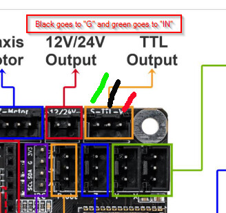
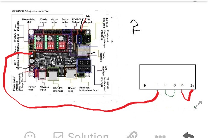
This represents your TTL Output on the DLC32 - [S,G,V].
S → PS In
G → PS L
PS P → PS G
Are you only focusing on CO2 PWM signaling?
This represents your TTL Output on the DLC32 - [S,G,V].
S → PS In
G → PS L
PS P → PS G
This should work, I think something isn’t configured correctly. I think you have beat the hardware to death and it seems it’s working, but it isn’t working in a standard configuration.
Do you have a volt meter? A scope would be great, but a voltmeter will tell you what you need to know. You can check the inputs to see what’s happening. That would be a good next step to figure out what’s happening.
Your connections should be valid, we need to look at the signal.
The G → lps L should be the same as grounding the three pins.
With these components you need a common ground, no matter how you build it.
![]()
i also made this schematic and it doesn’t work, connected S to In and TTL to L, it doesn’t work, power supply is not broken, if i connect mks sbase it works max 15 ma, i think this power supply is for the ruida DSP controller
Can you put a meter on the S and G of the TTL output and make sure you’re getting a 5V TTL?
I keep asking him that, but he seems convince it’s not wired properly.
I’m starting to think he wants to see it’s smoke.![]()
![]()
Everything I’m saying here has already been said, but sometimes one little thing will ‘click’ if you see it phrased differently, so I’m going to try to help as well.
If this is still a thing, there are exactly two wires that need to connect from the MKS to that power supply.
Power supply
MKS board

If you are powering the MKS from that supply as well then you’ll have to manage that.
Connect “K-” to “K+” to enable the laser. Disconnect these two to disable. Wire a switch here, you can’t see the beam and really ought to have a way to be “sure” the laser can’t fire.
Ignore “L”. You don’t need it. I’m ~90% sure that the “K+” and the “L” connections are just two connections to the exact same circuit internal to the power supply. Maybe, maybe not, I’m still digging for info on this.
You will now have PWM control of your laser power from Lightburn. The front control panel won’t work and you won’t need it.
Essentially your CO2 laser will now operate like a diode laser with Lightburn having full control of power.
If you don’t have one, then I’d strongly recommend installing an ammeter so you don’t overdrive your laser tube.
Good luck on your project.
mfl_ir it does not work with your scheme, I managed to connect L to spindle minus, so it works at most 15 ma, with the mks sbase and skr 1.4 the same, more than 15 ma it does not work

Hey, thanks for the feedback.
I have that board hooked to that power supply, and from my notes what I posted above is what I did. I’m out of town for work until thursday evening, but friday after work I should be able to have a look at what I did and I’ll send some pictures and fix my above post with whatever is wrong.
Hello, I had a chance last night to take a look at what I have done and what I said above is exactly what I did and is working well for me.
I’m not sure about the 15ma part, I haven’t run across anything I wanted to do that wouldn’t cut or burn at 10-12ma, so I haven’t tried for more. I may do that this weekend just to see if it will.
I’m not sure what’s going on if that wiring isn’t working for you, but if you’ve gotten your laser running then that’s all that matters really.
Here are a couple of pictures of what I did:
The other end of the blue wire is cut for 24v power and the rest are taped over and laying in the bottom of the machine, not connected to anything.
If you are using DLC32 v 2.1
The TTL Gnd is a pure grnd.
It is not working to control the laser.
Instead, use the Spindle’s Gnd to the L.
This topic was automatically closed 30 days after the last reply. New replies are no longer allowed.