hi folks, i got a mks dlc 2.1 card. i tried to connect to a 50w laser you have 2 swicth holes but the laser does not turn on, there are 2 mks dlc versions? I attach photos of power supply and mks dlc
I understand that you need to buy 8 bit version, mine is 32 bit
I’m confused. MKS DLC 2.1 is an 8-bit board is it not? But then you posted a picture of MKS DLC32.
Do you have the DLC32?
yes that’s right, I published the photo of my mks dlc 2.1 32 bit card, the scheme is wrong, can you tell me how to connect my power supply?
@killrob is very familiar with this board and may be able to help you.
1 Like
Is only che laser that does not turn on or the entire controller? You have connected the power switch but the power Jack?
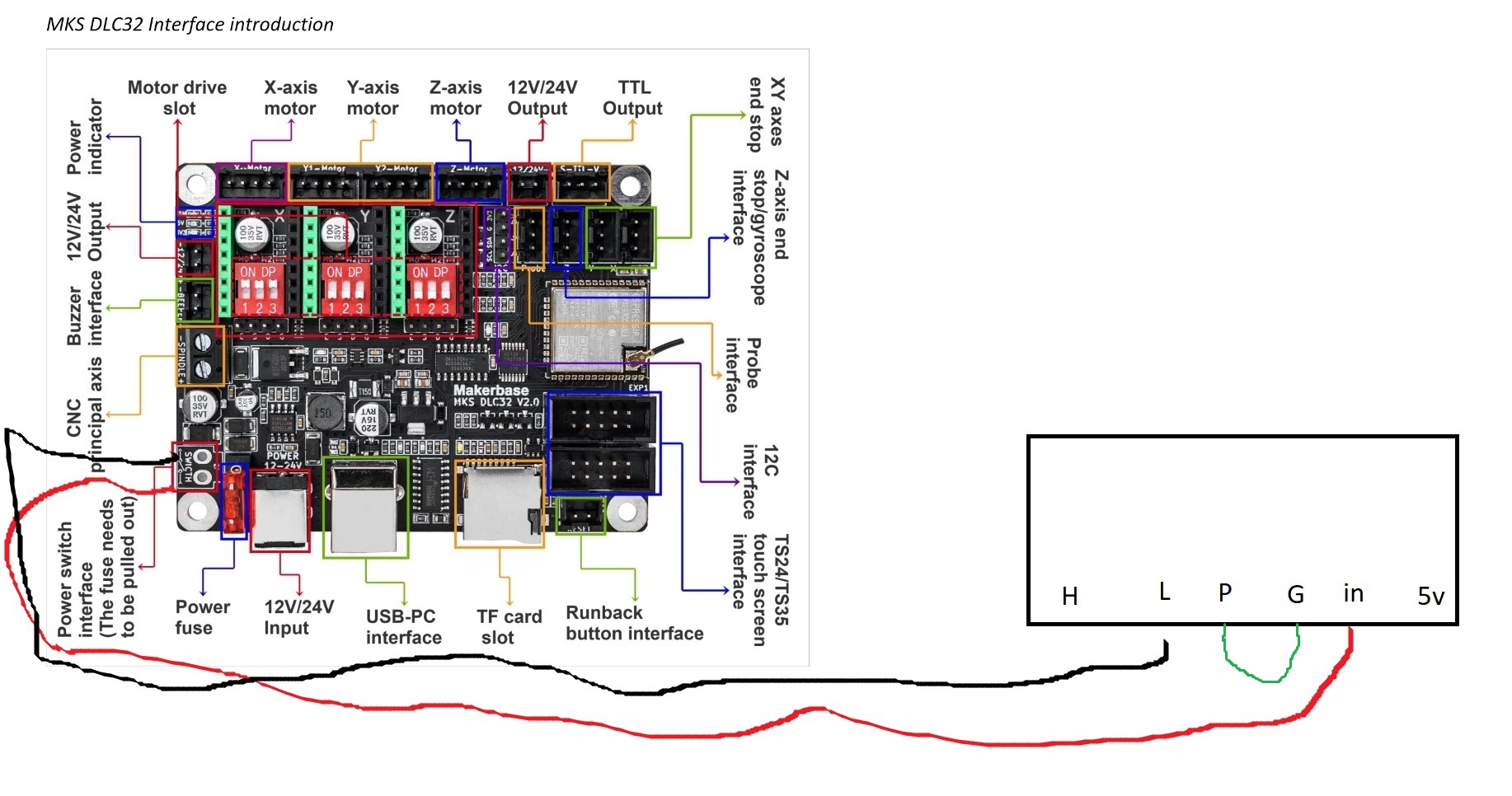
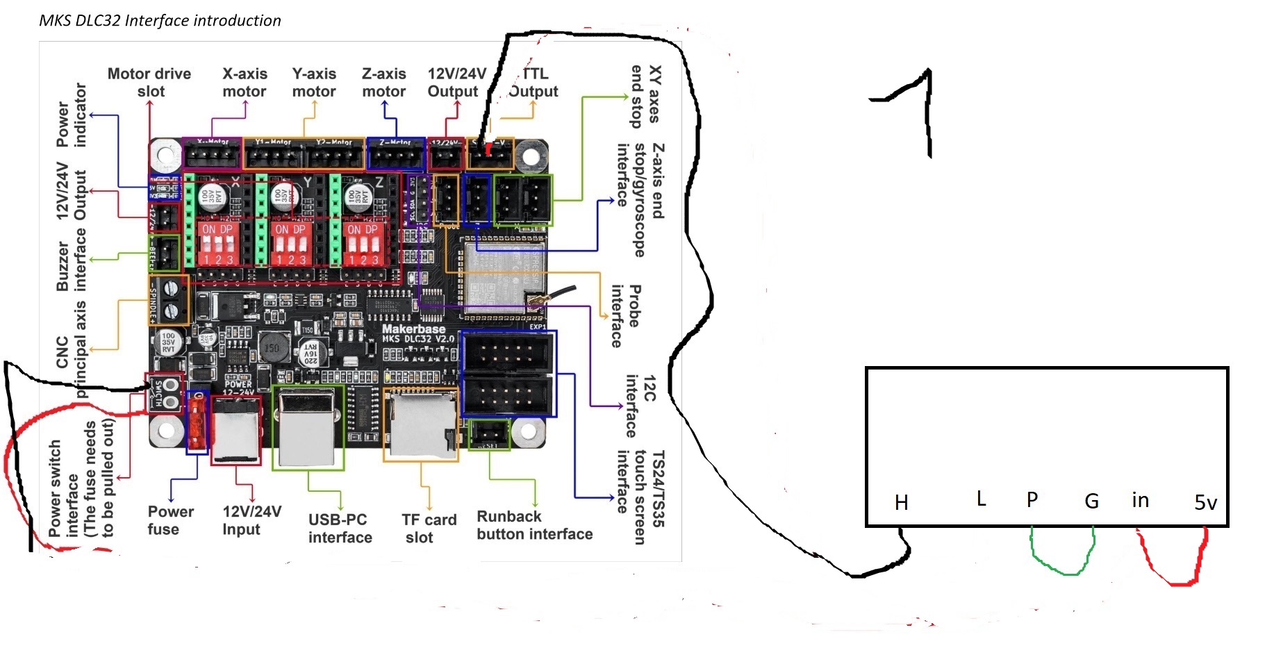
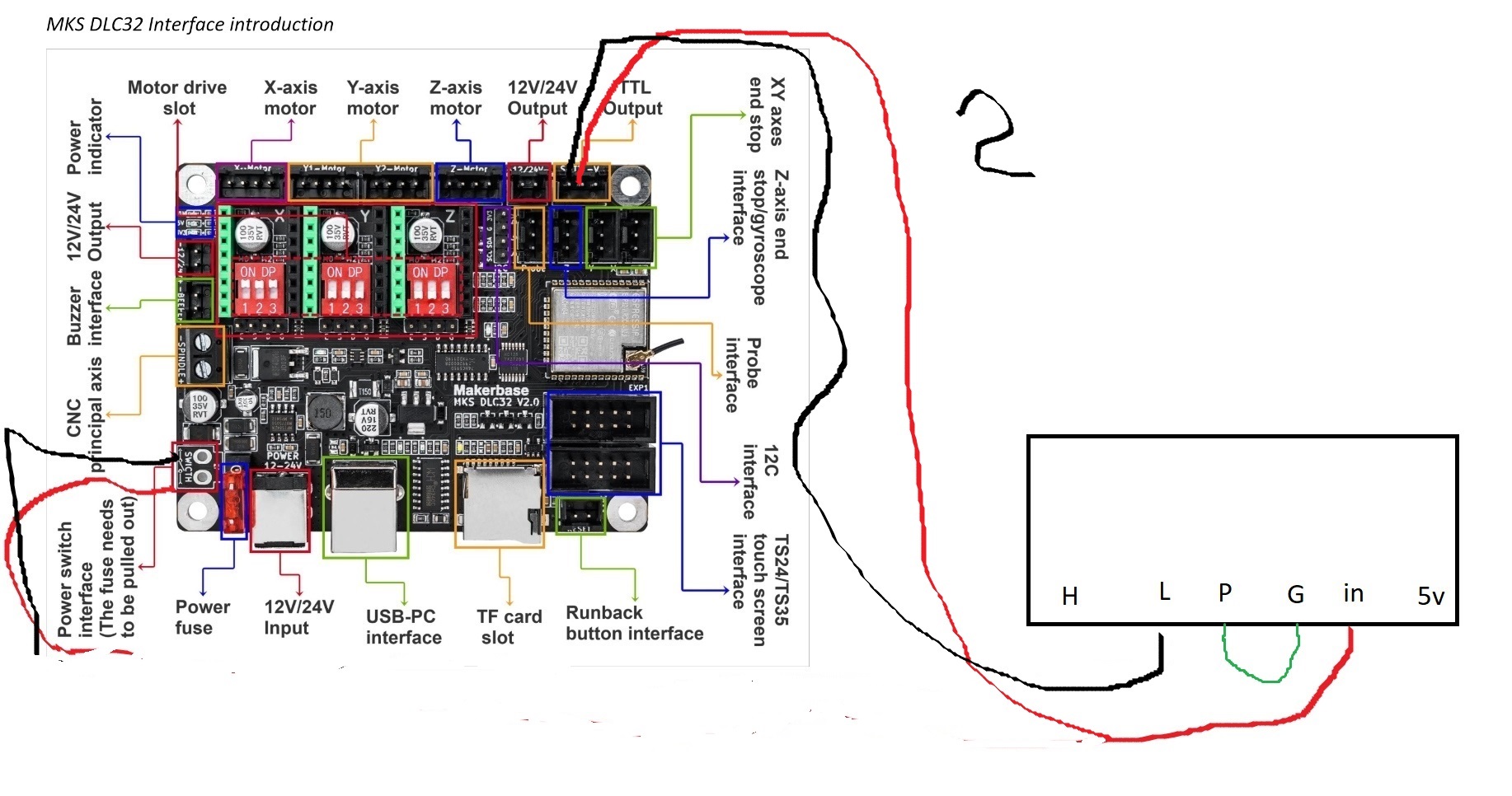
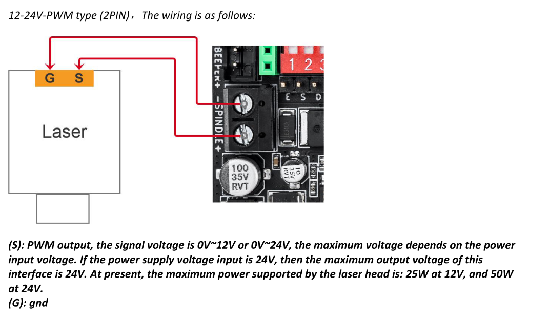
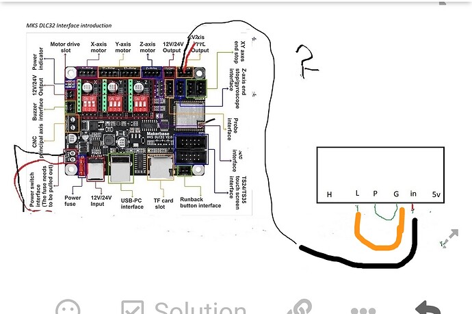
the controller is ok it turns on, my 50w psu is different from that of the k40, the mks dlc 32 have moved the TTL to the top right, I made scheme 1 and the laser reaches maximum power 12 but, I made scheme 2 and the laser does not turn on
Did you get the technical manual for this board?
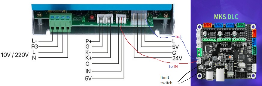
You need three lines to the lps, assuming a common ground.
PWM → IN
laser enable → H (high enable) or L (low enable)
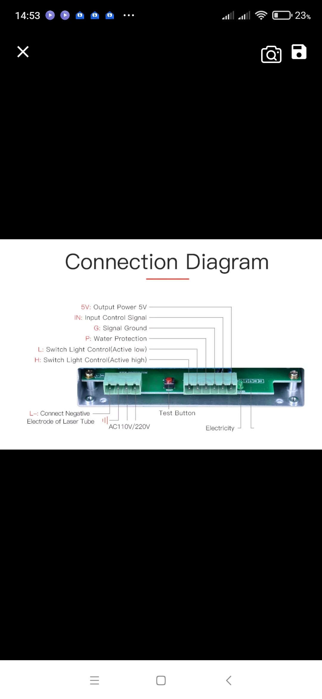
P is usually the water Protection and is normally, active pulled low. If there is no water, this will prevent firing.
This may be a better connection for your pwm.
There isn’t an obviously labeled ‘Laser Enable’ output, so you have to hunt that down. You can strap L to ground, but I don’t recommend it. It’s like a safety on a gun, if it’s not off it won’t allow it to fire. If you ‘manually’ bypass that safety option… it’s you skin…
I don’t really know this board and it’s output voltages are higher than I expected but it’s a common replacement for the K40s.
There is some discussion here about the voltages.
Ran this down on this site… but it’s not very clear to me… how they have H & L handled, which I think is K- & K+…
What are you doing with the power connector? This is probably not what you want to use…

Good luck

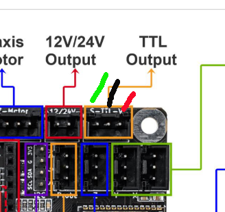
The thing is that the v2.1 has moved the TTl to top right corner and now has three pins vs two on the original release.
It does not change how we connect the board.
I am connecting the board with a dedicated 24 v power supply and it needs to connect the GND from the new power supply to the GND of the Laser’s power supply.
The TTL GND TO K40’s Power supply’s L and if you want to drive the laser using PWM then connect the TTL’s S to the IN ON LASER’s power supply.
I am installing a two way switch, so I can decide when to use PWN AND WHEN TO USE FIX LIMITING LASER POWER OUTPUT.
50w power supply is different 40w k40, it does not have 24v and where it is written 5v it is not 5 volts, I made scheme 2 but it does not work
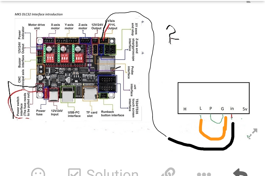
If you meant PWM to be the only control, L, P, G can be tied together and grounded. You pwm goes to the IN control. The P input should be your water protection input.
You have the PWM Wire to ground and attempting to enable it with the L input. You have grounded the IN input essentially disabling the lps. Yes, it will never fire. You are making this awfully complicated…
Do you know which pin is which on that connector… doesn’t appear so.
I read this connector as
Green -> pwm signal      --- marked as 'S' (signal)
Black -> ground          --- marked 'ttl' as the type of interface, ground maybe needed so it's here
Red   -> V               --- supply voltage
You have to have the supply and all associated parts with a common ground to get the signals around. I would think you would only need the PWM from that connector to the IN of the supply.
With what you have done to this board, I think you are lucky it still lives… ![]()
Good luck
![]()
I am with you!!!
The incorrect wiring could have cause BIG issue ( if not already).
When using the external power on/off switch to the board, you must remove the fuse.
Use multimeter to find out what is grnd what is live +.
Before plug in cables to any device.
Good luck
i did no damage, laser and power supply work fine, make a right diagram to connect my power supply with mks dlc 32, remember my power supply is different from k40
I don’t have a K40 either… But it’s the same game…
I’m pretty sure you’ll find they are as I marked them. The normal ss laser has a ground, power and a pwm signal in the cable… This would fit with that connector. Lasers with a heavy current draw shouldn’t use this source for power.
The connections are pretty simple, P is water protect, G is ground, L is ‘Laser Enable’ (used with the DSP controllers) and H is the inverted input for L. If you controller has a ‘laser enable’ that goes high for active.
Good luck
![]()
Can you confirm the type of laser you have?
If I recall, he’s upgrading the controller on a k40 type.
![]()
mine is 50w power supply plus 50w laser tube, it is self built laser, is this schematic right or not?
What is the specific make and model of power supply and tube?
How are you supplying power to the tube in your diagram?
no matter laser brand, vevor 50w tube and psu 50w myj50, even this scheme is not good
last appeal, is there anyone who knows how to connect this controller right and can make a diagram drawn? thanks