I am brand new to the Lightburn platform. I am working on my Ph.D. work on laser materials interactions (mostly 3D printing by melting reactive powders) and found that the combination of Lightburn and a cheap diode laser makes a nice benchtop setup. I have done some preliminary research related to these questions on the forum but was hoping for some clarification as it relates to the Orthur Laser 20W.
1.) Is it possible to enable constant laser power to make a continuous track (not discrete irradiation of points). I looked into the continuous jog mode settings but it appears that was what I was looking for.
2.) Is it possible to determine the pulse duration (through the g-code) for “pixel” irradiation if it is discrete? I previously had a NEJE Maser with their software (which was limited) but it had function for laser power and pulse time (1ms-100ms), but not scan rate.
Last bit of info; I get the hghest power density possible(Watts/mm^2; I can measure Orthur Output in the lab if anyone is curious). As such I will be focusing a beam then rastering a sample region of 1cm^2 from a “black square image”
In anyone has suggestions for software, settings, etc that would be awesome!
All controllers use PWM (pulse width modulation) for controlling the the power output to the laser. If you set the power in LightBurn to 100%, and the settings in the controller firmware are normal, the PWM will be “on” the entire time with no pulses at all. If you use the GRBL-M3 device in LightBurn, instead of choosing GRBL, it uses the M3 (constant power) command, which does no ramping of power at all - just fixed, constant output.
Thank you Oz, I appreciate the prompt reply. I tried the same thing with the NEJE but still got pulses at 100% power with PWM. Also is pulse duration listed as “$0”, “step pulse”?.
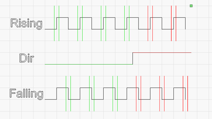
step pulse is a transition from low to high, or high to low. The controller will hold the line low, and pulse it high, or hold the line high, and pulse it low. The transition itself is what matters, and motor drivers will either look for a transition from low to high (rising edge) or high to low (falling edge) to accept as a ‘Step’.
If the laser controller believes that the motor driver is looking for the leading edge signal (when it transitions from low to high), it will pulse the line, and could change the direction line immediately after that. If the motor driver is waiting for the falling edge, it will see the direction change BEFORE the falling edge of the pulse, meaning that it will change direction one step too soon.
In the image above, the upper line of steps is interpreted as 4 steps in one direction, then two in the other. The lower line is interpreted as 3 and 3, and the only difference is which side of the step signal the driver is looking for.
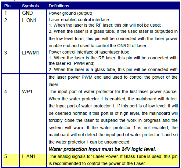
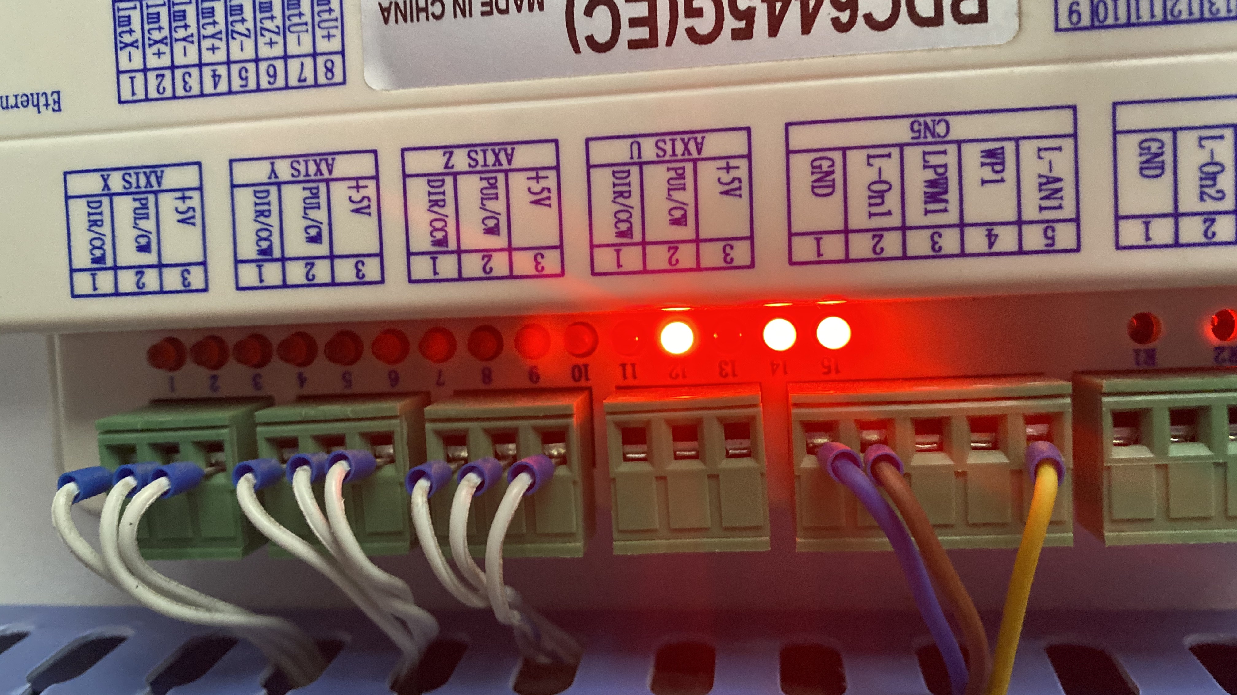
I am not sure if this is helpful or misinformation, so please let me know. The Ruida controllers that I have used (6442 and 6445) provide both PWM and analog outputs.
So if you are looking for a non pulsed 0 - 5v signal (always on) from the controller, maybe this helps?
But your question sounds to me that you are after controlling whether actual laser light output (from the Diode, DC Excited Glass Tube, or RF Excited Metal Tube) is being pulsed or continuous. Am I way off here?