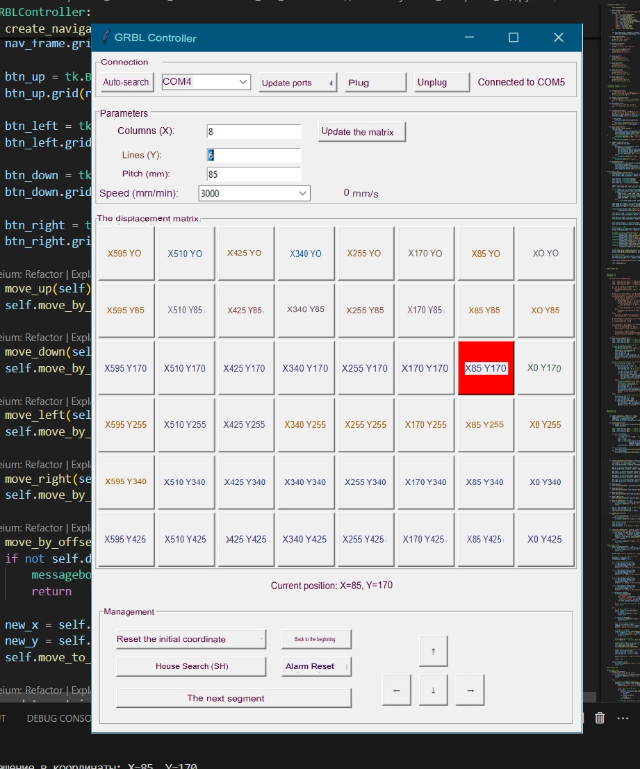
Another small addition. While I was finalizing the program and starting to write an automation script for AutoIt (and for this you need to learn hotkeys, which are not yet enough for full automation), I found a practically ready-made tool for work: since I did not use Lightburn together with GRBL, I had a poor idea of what capabilities and options the program has for this platform. It turned out that when using the alt+0 key combination, a tool is called that uses the “Move” window in its work (it can be called without any combinations - I was just trying to understand what hotkeys can give me). So, the lightburn already has a tool for simplified navigation on the GRBL workspace with tools:
Control of the step of movement
Control of the speed of movement
Search for “home”
Convenient manual positioning for control from the keyboard (Jog)
Fixing coordinates (including the formation of a convenient list of working coordinates)
You can open a separate lightburn window and select the “Move” option from it as a small control block next to the JCZ control.
And the most interesting thing is that in general it is quite easy to switch between the GRBL-JCZ-GRBL-JCZ interfaces to go from navigation to engraving and back. No lengthy initialization is required, it is enough to simply select the neighboring device. This is still not as convenient as it could be, but by and large it is enough for a number of tasks.
Because my work can contain dozens and dozens of dozens of processing segments, this is still not very convenient, so I will continue to tinker with automation macros and a program for navigation, but in general for those who solve simpler problems, this looks like an ALMOST ready-made solution (after all, it is still necessary to switch devices, then call navigation windows, control movements, etc.)
Yes, I mentioned it in the picture. Yes, it’s still inconvenient, but it’s definitely a working option.
For those who want to automate lightburn via AutoIt - pay attention to the LightBurnJobs.csv job log file: unfortunately, the program interface is not implemented using standard Windows tools, so it is impossible to bind macros to inscriptions and pictures, buttons, and hotkeys do not work as well as I would like (for example, I can physically assign more than one hotkey, but they will not work, localization of hotkeys is extremely important - at any time, if the keyboard layout is not English, the hotkey may not work), so you have to look for workarounds. One of such ways is to activate the job execution log (LightBurnJobs.csv) and track the file created by the program. Now I control how many lines are in it and clear the file to move on to the next engraving segment. Conventionally, if the number of lines exceeds 150, this is a sign that the engraving is finished. This is the only sign of a completed segment engraving task, unconditionally accessible at the system level (it is simply impossible to bind macros to lightburn interface elements). Without an API or some short, compact log file that is not blocked by lightburn during operation, automation is very difficult.
While I am experimenting, I have discovered a series of program shortcomings that I no longer have the strength or motivation to officially write about: when using the “Repeat marking” menu, which suits me much better than the standard engraving launch dialog, the laser always passes through the “start” coordinate (the center of the work area) between repetition cycles. This is not very correct and takes time with hundreds of repetitions. But what is very convenient and correct is that the sound of marking completion when launched through the “Repeat marking” menu is played only once (in the standard dialog - as many times as you specify repetitions). I also wanted to bind an automation macro to the event of the “Checklist” window appearing, but this window simply does not appear when using “Repeat marking”.
Why use “Repeat marking” then? In order not to set the number of repetitions manually. Through “Repeat marking” I can simply press a hotkey (I assigned F5), then F2 and the engraving will be performed as many times as I assigned earlier. And this will work tens and hundreds of times. Even after restarting the program, there will be as many repetitions as I assigned earlier.
In general, all my work is a circus and clown show, you don’t need to do this. It is better to buy a controller for working with EZCAD + 2 expansion axes X + Y. But while I have enough strength, I will continue due to stubbornness.
If someone needs my developments, I will easily share them, but I am afraid that figuring them out will be even more difficult than it was to make all this work somehow
Surely a comment like this will make them want to jump up and solve your production issue. You don’t win friends by spitting on them.
@jkwilborn said the reality of the situation in Post #10. If you have a workable solution already, please share it here so any one else with a Galvo and an X/Y table can benefit from it.
Wanting to use a linear table with Lightburn (one axis only) can this be done using the rotary setting’s with the circumference being the length of the table or does it have to be a repeat marking for a linear table
I haven’t tried but no reason it wouldn’t work, slice distance would move the table a set amount, a section of image would be burned, repeat. I see two reasons to do something like this, one, long workpieces, the table would need to have more travel then the lens field width to have any value. Could use large slices I would think. Two, you were trying to burn deep enough to cut, and didn’t want the beam angle on the outer edges. You could keep the beam perpendicular to the table while cutting a larger area. (Lengthwise, anyway) Small slice.
Have to think through and/or experiment to determine circumference setting, slice, and steps per rotation. Let us know your results, I, at least, am interested.
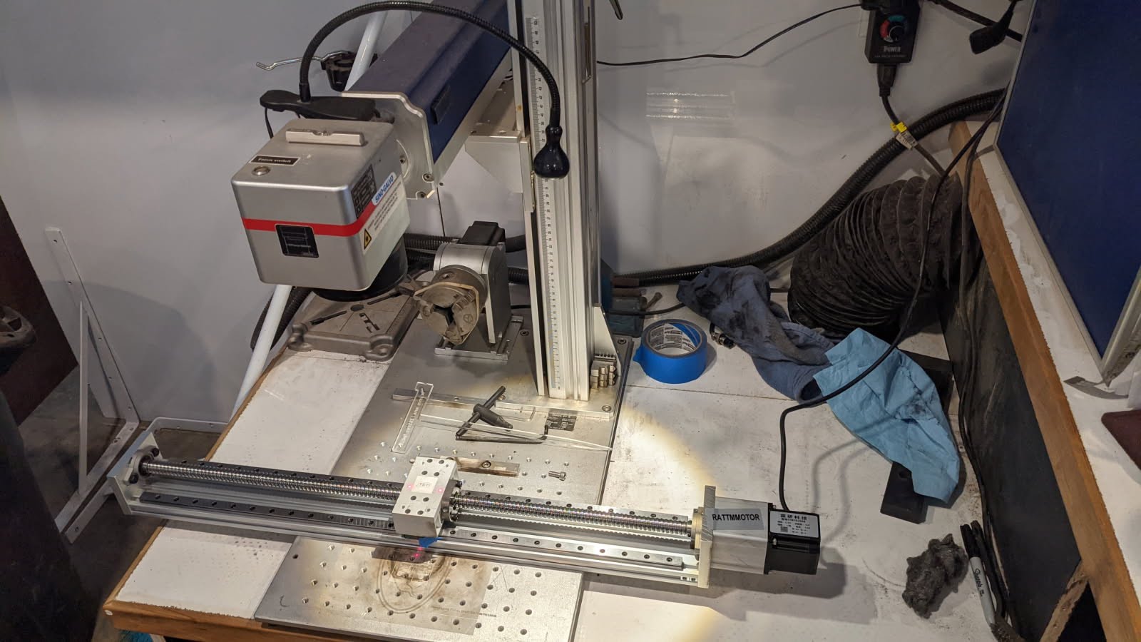
I am working on the same thing an purchased a linear actuator with a screw gear. I am able to jog the entire 24" stroke that the actuator offers but when I run a job it jogs about 3" runs 3" of the job then jogs back and runs the next 3" of the job right over what it has just done it continues doing this until the entire job is done. I ordered a belt driven actuator that is not geared way down like the screw gear one is. For the screw gear actuator I had to run it as a roller rotary with a roller diameter of .06289" if I se it as a chuck rotary I have to set it at over 6 million steps per rotation. Definitely let me know if you find a good work around
The linear you have in the photo should work fine, you are doing something wrong with your settings. (IMHO) Looks like a 5mm pitch so example
Say your DIP on the microstep driver is 6400
Say your max travel is 24" so even number 600mm.
Say your screw is 5mm pitch
So 6400 steps move 5mm. 768,000 move 600 mm
Make your circumference 600mm, steps per 360 768,000, slice whatever 25mm?
If LB won’t allow 6 digits in the steps per 360 field have to set DIPs for something smaller.
Not at home now so I can’t check this maybe Im missing something.
Albroswift, I really appreciate your input! I understand the concept of what you are saying although I have not up to this point messed with the driver on any of my devices. This project is venturing into new territory for me so please bear with me as I attempt to understand everything. I have an OMTECH laser and the rotary driver is internal so its not easy to get to to make changes. I do use my standard rotary quite a bit so I would have to change my dip switches each time I switch from one to the other which would mean opening up the laser case. I know that would not be the end of the world but still a lot of hassle. The pitch according to the manufacturer is 2mm. In your opinion will I be better off with the belt driven actuator with a Higher gear ratio or Is there an easy way to have a separate driver for each rotary device I have? Attached is the link to the bet actuator I have coming. Maybe I’m looking at this all wrong.
If you know the steps the microstep driver is set for, just change the numbers in the rotary setup screen.
2mm pitch is a very fine pitch. Typical is 5 and fast is 20. What are your dips set for now?
You are correct I just measured the screw with calipers and it measures exactly 5mm thread to thread. I am currently running a job but will open up my lasers case and check the setting when I am done.
So I just opened the case of my laser and my driver is set to 12800(duh, I should have known that as that is the value I use for running my standard rotary) I adjusted the dip switches and set to the parameters you gave but when I start a job lightburn seems to get a headache it just sits and gives me the spiny circle and my computer tells me lightburn is not responding. I lowered it one step at a time to 1600 and that brought my steps per rotation to 192000 now it works. I’m wondering if it is lightburn or my computer that cant compute? Thank you so much for all the help Albroswift. If i can bother you a little more, What is your recommendation? Use the screw actuator or switch to the belt actuator that would potentially be a higher gear ratio? If keeping the screw, then do I mount the driver externally and adjust the switches whenever I switch between my rotary and my x-axis table or do I keep another driver with the setting I need and just swap out the driver? Lastly if keeping the screw is there a way to add a second driver to lightburn and just select which one I am using within the program?