Control of the X+Y worktable for galvo lasers

There are two big problems:

  1. LightBurn does not support a two-axis extension table for galvo scanners (this function is implemented in conjunction with EZCAD2 by the SplitMark2 plugin)
  2. Few controllers support the use of two axes simultaneously, which reduces the number of devices that can be used this way

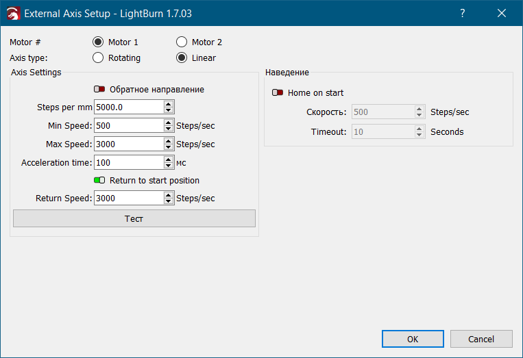
Within the first problem, LightBurn has a solution for working with rotary devices, which is the first step in implementing a full-fledged single-axis table. In addition, LightBurn has long been able to control classic two-axis lasers.
But the second problem, unfortunately, makes it pointless to develop a TWO-axis machine for Galvo, because few will be able to use this function because most lasers are equipped with the cheapest control boards that do not support two X+Y axes.

Potentially, this problem can be solved even with just one axis - signals for X and Y control can be sent using the same output, you just need to split them into “portions” - separately for X and separately for Y.
OR
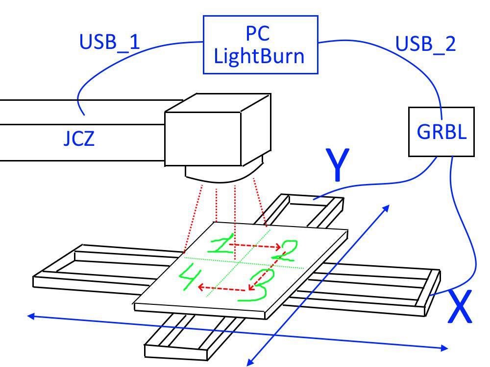
You can simply control another separate device (based on GRBL, MACH3, etc.) and make a software split: first a series of signals for the X axis, then a series of signals for the Y axis, because there is no need for diagonal movements on such a machine (the working area is divided into a grid of 2 * 4, 3 * 6 separate segments, to which the machine can be positioned, you need to send only a few coordinates - 2/4/8, depending on the settings and table size). Thus, all that is required from LightBurn is to make a micro API / console / record in a file of Gcode control commands (for example), which could be used by a third-party controller and would allow moving the desktop in the desired direction. And, of course, it is necessary to solve the problem with the correct movement of the laser machine taking into account the error and the selected processing segment, as SplitMark2 does, because galvo lasers do not work with a point, but with entire areas (70 * 70 mm, 110 * 110 mm, etc.)

In the simplest form, I see it like this: LightBurn generates control commands for an additional USB controller, the controller reads them from the buffer / file / API channel or receives them directly via USB, the desktop moves in the form specified by the command (which has long been supported by LightBurn), engraving occurs, then LightBurn sends the next batch of commands to move the table to position “2”, to a new place, and engraving is performed again, after which the movement to position “3” is carried out.

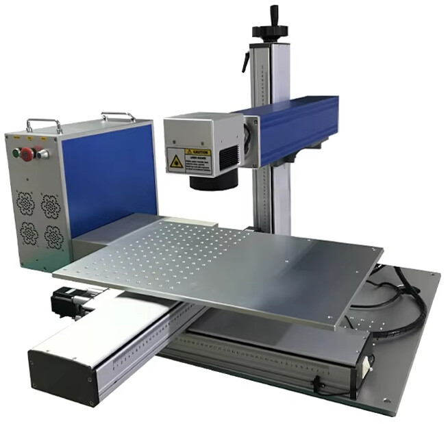
Perhaps this is too ambitious for the LightBurn team, but it would be a truly unique offer on the market - a controller that can solve this problem on its own would cost at least $500-700 (just because of the extra axis, I’ll have to buy it for work), while the quality of the EZCAD2 software that I’ll have to work with is unlikely to satisfy anyone. A controller for EZCAD3 would cost more than $1200. And that’s without taking into account the mechanical components. If you follow the described approach, it is enough to buy or use an existing two-axis machine (I know that almost everyone has a machine that they started with :slight_smile: ) on MACH3/GRBL ENTIRELY for $ 100 and get a function that only expensive devices can boast of

Perhaps someone already has such developments - then I would be glad to learn more about them. As far as I can tell, Albroswift is a user in this area – it would be nice if he has something to say about it

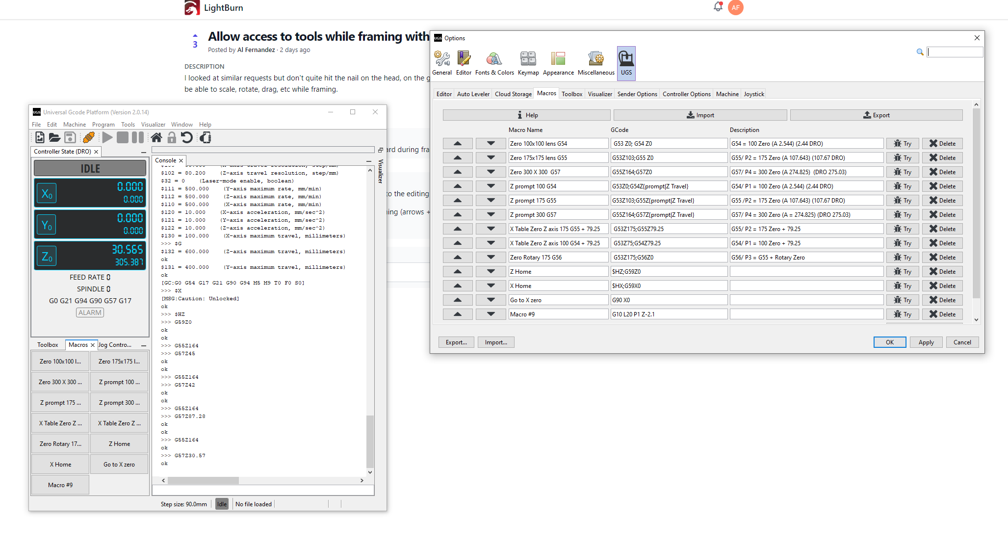
Here I saw a note on this matter, but the discussion is already closed:

1 Like

These machines don’t use grbl.

I understand EZCad3 boards have an encryption mode they run in, so that has to be reverse engineered before they can even look further.

If you’re advocating Lightburn in some kind of hack to use two control boards, I doubt that’s going to fly either… you end up with unique hardware between user models.

:smile_cat:

I don’t understand what kind of hack you’re talking about, the program just needs to control two devices in parallel: the JCZ controller and any controller that supports two axes - for example GRBL, both of which LightBurn already supports. All that’s left is to coordinate the internal infrastructure of the program

As for EZCAD version 3 - I mentioned it simply as an example of too expensive and unnecessary equipment for implementing the described task. In general, EZCAD2+splitmark2 already know how to work with two axes

The uniqueness of the solution in this case is that a galvo laser with the cheapest JCZ controller (or even a copy) for $150 + a GRBL controller for $10 will allow you to work in modes that are only available on much more expensive equipment configurations ($500+)

Running two controllers.


The true issues is usually Lightburn has no information about the controller or any existing codes/control values that are available to be used. The Chinese won’t tell them.

This has been asked about, I’d think if it was an easy implementation, it would have been handled by now.

:smile_cat:

A Texas laser company makes/sells a galvo/ gantry laser, spendy though. Similar concept.

Maybe the problem is that English is not my native language, but I still don’t understand what the JCZ controller signals are for. If LightBurn can already control the galvo laser task and can already control GRBL, then why can’t it control JCZ + GRBL in parallel? Maybe it will be clearer if I describe the general scheme:

  1. The layout of the task is prepared in the LightBurn program, which is obviously larger than the working area of ​​the galvo laser (for example, a 200 * 200 mm layout when using a 110 * 100 mm working area / lens)
  2. The LightBurn program divides the large 200 * 200 layout into smaller segments, for example, 4 blocks of 100 * 100 mm
  3. LightBurn, using the GRBL controller, moves the table to position 1
  4. Standard engraving is performed within the 110 * 110 mm working area by sending the task to the JCZ controller
  5. After completing the engraving of segment 1, LightBurn, using the GRBL controller, moves the table to position 2
  6. Engraving of the next segment is performed
  7. […]

Yes, there is a problem with alignment and nonlinear distortion of the working area (strong distortions closer to the periphery of the working area), there are difficulties with the correct division of the image into segments, but all of this is algorithmic and in general the entire base for this has long been in LightBurn

This is the problem - in essence, to implement this task, no complex electronics or significant power are required, there is simply a task of coordinating the existing capabilities of LightBurn.
In principle, this problem has long been solved on Chinese software, I think this happened at least 10-15 years ago (when the SplitMark2 plugin was released)
The main problem would be the algorithmization of image division and distortion compensation (using SplitMark2, for example, I select segments much smaller than the working area - 25-40%, to avoid distortion). But this is already a much less significant problem, if there is some kind of software base

I think the issue is LB doesn’t really “Control” the laser, it sends instructions to the controller. After that LB doesn’t get any feedback as to how the controller is executing the commands or where in the string of commands it is. It knows when the buffer is full, when it is done sending instructions, and it does know when the laser is done and back to ready state.
In your example above the artwork would need to be split and stacked on 4 different layer sets on top of each other, or moved simultaneous with the table move. Otherwise you are just doing repeat marking. (Which LB handles very well). Maybe we should start with repeat marking plus something like variable text with but with image segments.

1 Like

It seems to me that the controller gives some feedback about the completion of the task, otherwise how would the program even know that the task is completed, how could it repeat, much less endlessly repeat the sent task, move on to tracing after the task is completed? Feedback in the form of the completion of the engraving comes - that’s enough.
In any case, the described idea comes down to performing a series of separate (segment) engraving tasks, with the execution of simple X+Y positioning commands between these tasks


I repeat: I am not interested in smooth movement on the X*Y table right during the execution of the JCZ command (that would be too much). We are talking only about episodic movements between segments (in my example, this is only 5 movements and five lines of Gcode: moving to the starting point from any position, moving to the 2-3-4 segment and returning to the starting point)

You’ll have to wait for someone from Lightburn to answer this to your satisfaction. None of us participating in this discussion knows the intimate details of how Lightburn actually work internally. You are making many assumptions about how Lightburn functions internally, true or not.

This is also not standard hardware/controller, as anyone can hook this hardware up, meaning it’s non-standard and would require configuration. This leads me to referring to it as a hack, not to be offensive, but it’s to solve a specific issue that only a few people have.

Hopefully one of the development people will sound off about this and clear the air.

At the top right is feature suggestions that you can post and let us vote on it… maybe you should post your idea there and see how many people are interested.

Good luck

:smile_cat:

I’m not sure what assumptions you’re talking about - I was just describing the concept. It involves using LightBurn’s existing capabilities. Of course, none of us can know what it all looks like “under the hood”, but I’m not a developer to worry about that, I’m an ordinary user who lacks some of the program’s capabilities
But you’re right about one thing - there’s little point in wasted discussion here

Hang in there and see if one of the developers will reply as to what is possible and what isn’t.

I still suggest you post in the feature suggestions, maybe you’ll get a better/quicker answer.

:smile_cat:

Wasn’t wasted on me. Post a feature suggestion I’ll vote on it.

Ok, I did that
I just wanted to discuss some general details before pestering the developers, in case other users already have some projects and working solutions, but the whole discussion boils down to “we don’t know how LightBurn works” and “it’s better to ask the developers”
Maybe that’s really the only way

Controlling additional X+Y axes for a galvo laser with an external controller (GRBL, MACH3, etc.)

I believe that is already in the oven.

It seems like this is some kind of private page - I can’t view this link

Sorry posted an old thread.
Updated with the correct one.

Yes, I saw this topic, but there is little information, including how it will be implemented. If we are talking about “simple” control of the JCZ controller with support for two X+Y axes like the JCZ LMCV4 - this is unlikely to be a popular option, because such controllers are quite few and expensive. This is one of the basic problems

To sum up. As it often happens – it is always better to do everything yourself.
The task I outlined above is indeed solved quite simply, although without a single software shell you have to perform many actions and “disrupt the focus”. In essence, for those who may be interested, my path can be described as follows.

  1. Developing an algorithm (CorelDRAW macro) for automatic(!) splitting of a composite vector image (from many objects) into “processing clusters” using a simple rule: everything that intersects the cluster contour AND is nested in a cluster is grouped into a single cluster. The cluster size depends on the user’s arbitrary choice and the limitations of the machine’s working field size (the smaller the cluster – the higher the accuracy, but the more complex and multi-component configuration of working segments, which complicates the work). The weak point of the current version of the macro is that large contours intersecting several clusters interfere with splitting – they have to be processed manually, but at the current stage this is not essential for my tasks.
    So, the macro simply breaks the graphics into constituent elements (clusters) according to a more complex rule than just “cut and slice”.

  2. Developing simple Python software for GRBL with a GUI that allows solving the problem of simple navigation within the workspace by clicking on the desired segment/cluster. This approach greatly simplifies and speeds up navigation, while making it possible to customize the order of processing (unlike fixed-step navigation arrows in CNC control programs, where it is quite easy to get confused in the number of “steps” if there are many segments). A simple program generates a matrix of buttons/coordinates with a given step (15x15 mm, 40x40 mm, 80x80 mm, 110x110 mm – whatever) and the number of segments. Unfortunately, I have not found ready-made software that would allow you to quickly and comfortably create a grid of macros for movement (macro matrix) with the ability to quickly and easily customize the step and number of segments for different projects and lenses. It seems that there are prospects with CNCjs, but there is no ready-made solution yet.
    So, the program simply allows you to move to arbitrary sections of the work area. The current position in my example is shown in red for clarity, this is very convenient.

  3. Developing an approach to processing the layout within LightBurn. Here I see at least 2 approaches:
    – auto-centering segment by segment (hot key “P”), in this case you have to add an additional external contour to each segment of the layout, including the entire group, because the logic of the separator macro (p. 1) is such that the output group (cluster) of objects will almost always be asymmetrically larger than the boundaries of the cluster itself, precise centering in this case is impossible.
    – manual alignment of the layout in LightBurn as a whole without dragging individual parts. In this case, it is convenient to control the processing area, it is more difficult to mix up segments, the edges of the cluster frame stick well (although not perfectly) to the guides. More manual work and the risk of error due to non-ideal “sticking” to the guides, but the method works.

The workflow is as follows:

  1. The processed layout is “clustered”/split into segments with the required step by the macro.
  2. The layout split into clusters is loaded into LightBurn or EZCAD, the processing modes are defined.
  3. Using the software for simplified navigation, the step size and the number of grid cells are selected, navigation buttons are formed, the initial coordinate is determined.
  4. The processed segment/cluster is moved to the center of the LightBurn/EZCAD working field.
  5. Using the navigation software, the table is moved to the desired cluster by simply pressing a button.
  6. The engraving task is performed.
  7. The next segment of the layout is selected, placed in the center of the working area.
  8. Steps 5-8 are repeated

In essence, the above is enough to solve the work problem I am working on and discussed above. Although I am not a programmer or a developer, it took me a few evenings, a chatbot AI (for the macro code and the Python program), a Python runtime, CorelDRAW+VBA macros, an old Ardiuno UNO board with GRBL firmware, mechanics/electronics (for the XY table), LightBurn or EZCAD to solve this problem. Is the problem really that conceptually and algorithmically complex? I think not.

A couple more funny moments - when I tested the system, I learned that LightBurn already has a function of hotkeys-macros G-code for GRBL. They are not enough for comfortable work, but, by and large, the whole task could be solved only by the tools of LightBurn itself by running two copies of LightBurn. Splitting the layout according to the described rule (p. 1) = selecting with the mouse from the lower right corner to the upper left (without automation), controlling GRBL movements using “macros G-code” (p. 2) in the LightBurn console field. So, having gone this way, I can say that in reality there can be no limitations and difficulties with the implementation of all this on the basis of LightBurn, especially for professional developers.

Overall, I think I won’t continue to wait for my own solution from LightBurn developers, since the interest in this topic is apparently quite weak, it’s easier to implement it myself using external tools and automation macros, however, every time I see notes in the list of program updates about corrected localization and added descriptions, I will know that the developers are wasting time and effort on secondary tasks, instead of actually improving the product (and first of all, “product” is “functions”).

1 Like

Awesome stuff. I’m going to have to re-read a couple of times and then play around with it in the shop. Thanks for sharing.