I wanted to check mirror alignment but I can’t work out how my machine is set up to control the laser power.
OMTech 130w single laser, Mac OS Ventura via USB
Firstly, I found I can’t pulse from the control panel - pressing the button it has no effect regardless of the max power setting.
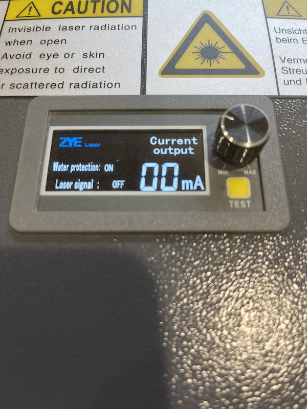
The machine has a real time laser power display on the left hand side with a “volume control” and a TEST button. The test button does fire a pulse.
However changing the maximum power setting at the control panel doesn’t seem to affect the power of the pulse, but the volume control does. In fact the volume control seems to be the only way I can control the power - if I run a job with the volume all the way down - no laser, at full volume it cuts fine but I have no idea if the power is correct for the job.
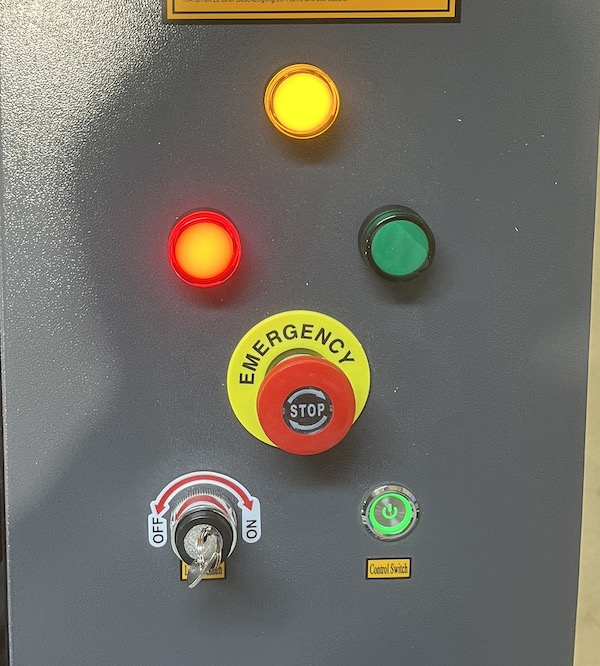
Finally, the green light on the control panel side never comes on - is this significant?
Can you post a link… to the machine?
The power meter is probably associated with the lps, but I haven’t seen one that is accessible like that on a machine like yours. You generally want the software controlling the power not a manual knob.
The test button probably drives the lps directly.
Is there any error messages displayed in the Ruida machine console?
Is this new?
As far as the photo, there are no labels on the lights, so I’d just be guessing. I would think a red light would be an error…
![]()
Not knowing which Ruida controller you have means this may not be exactly right, but it may be close.
In the Menu → Laser page I have a choice of Laser and Continue, with the former allowing a preset duration in milliseconds for each press of the Pulse button. Your controller may be set for a 1 ms pulse that can’t be seen and won’t make a mark on anything. Crank it up to 100 ms and it may suddenly start working.
You (well, I) can set power level for manual pulses at the main screen. Press Enter to start editing (at the speed settings), the ↓ arrow to select the power setting, then Enter to actually change the numeric value. I suppose you could set it to 99% and use the knob on the meter.
With the duration and power set up, you should get a decent pulse and can tune for best burn.
Thank you Ed, Jack
Laser is currently set to Continue > 0ms
I’ll try setting at 1ms and go from there.
I’ve tried a few times to reduce the power with the knob for mirror alignment but I haven’t succeeded in finding the sweet spot between nothing, or my painters tape going up in flames.
Do you think the knob controls total power output independently of Lightburn up to 100%, or up to the power level sent with a job, say 60% ?
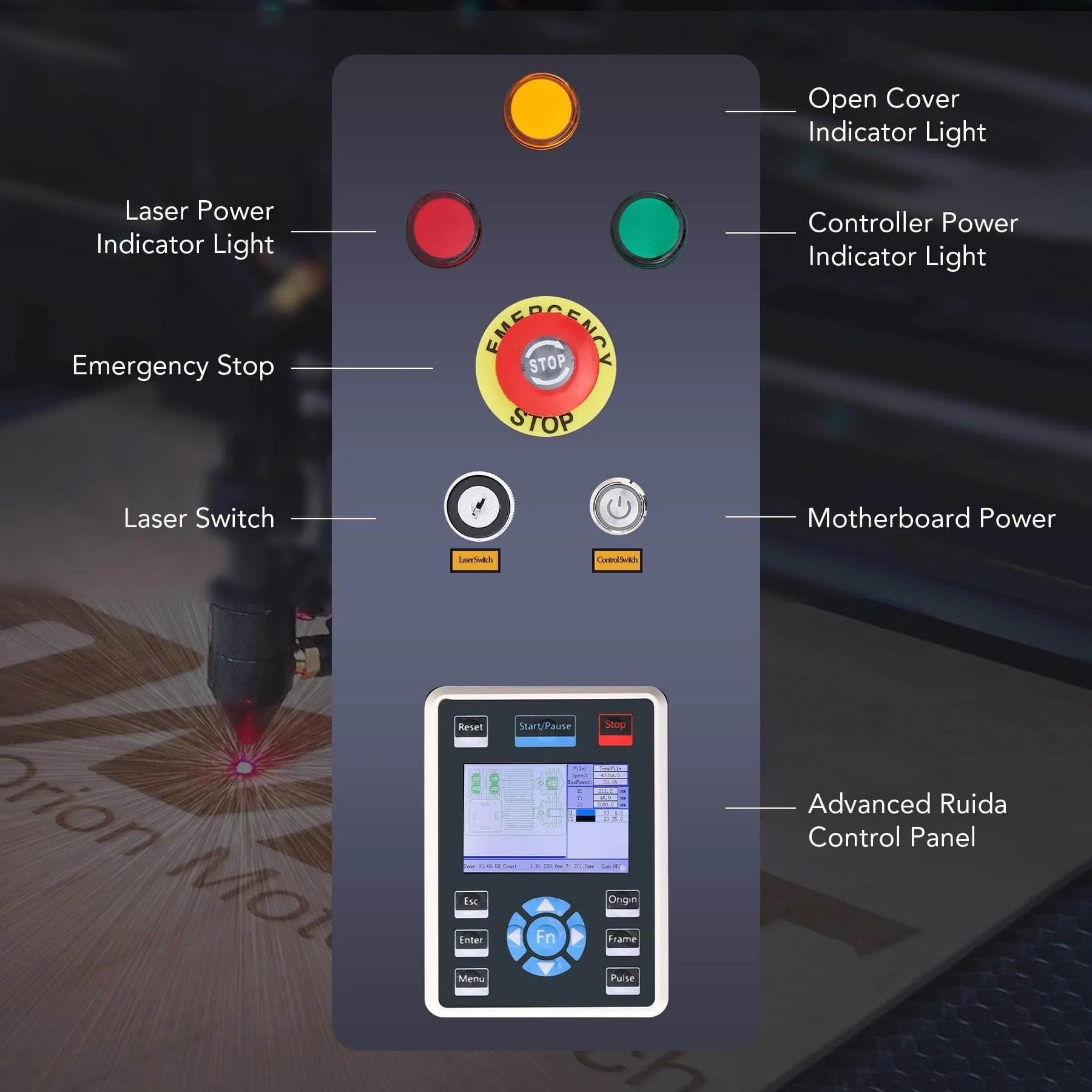
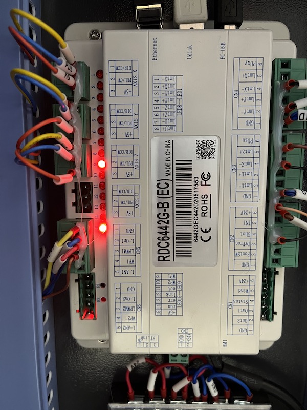
Jack, there’s no mention of the indicator lights in the docs but I found a photo on line which may explain.
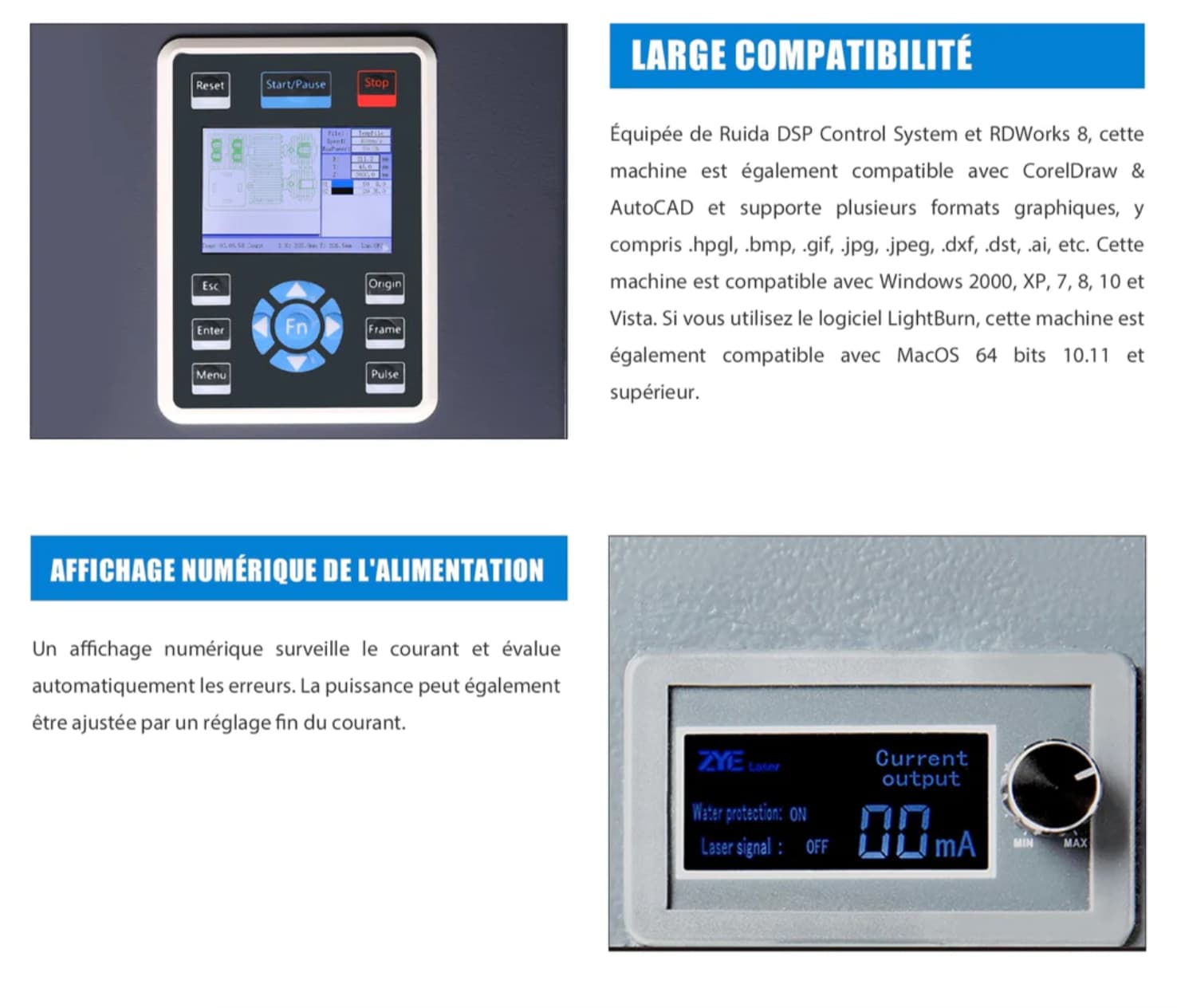
Here’s a link to the machine here in France - they seem to be set up initially for Germany judging by the warning stickers and docs.
OMTech 130w
As always, many thanks for your time
Which Ruida is that? It resembles a RDC7132.
Unfortunately the part I’d like to read, I can’t.
I’m assuming it controls the pwm (IN of the lps) for setting the max current… Digital meters for current jump all over the place during a job. if you are cutting at some power, it should be relatively consistent.
As I stated, I’ve never see a machine of this class having a manual power adjustment.
Most of us run analog meters to eliminate strange readings from it’s sample rate.
I would thin this would be a safe procedure … send a 50% pwm to the machine and set the pot to 1/2 (50%) the current you want associated to 100% power… This should sync 50% power in the software to 50% power through the tube.
There are also controls within the Ruida that you can set to limit the available range to the user.
Make sense?
![]()
I’ll find the Ruida model when I get back to the workshop.
Good idea for the tests, i’ll try 50% and 100% at the pot, and record the mA readout to see if it helps clarify things.
Don’t run 100%, just not a good idea under most circumstances, especially when you are setting things up…
It will synchronism your software with the power settings up to that, but be wary of high current…
![]()
OK will do, thanks for the advice.
It’ll take a few dozen milliseconds before the beam gets any traction, but you’re definitely on the right path now.
On supplies without the remote meter, a trimpot buried inside the case and accessible through a small hole should be set to the maximum current recommended for the tube, so that you cannot overdrive the tube and shorten its life.
I do not know how the knob interacts with that trimpot inside your supply: whether it allows complete control or only reductions from the internal trimpot’s setting.
If it were my knob, I’d set it to limit the current to whatever the recommended value for the tube might be (*), hot-melt glue that knob in place, then use the PWM values to control the power up to that preset maximum.
TL;DR: I don’t see much point in actively twiddling the current, particularly if doing so allows me to screw up and cook the tube.
Other folks have different opinions, but I find it easier to think of 100% PWM as “full throttle” for whatever the tube should handle. If the recommendation is to not use more than, say, 70% of that, then 70% is the maximum PWM you’d set for any cut, other than the occasional foray into absurd materials or stupid thicknesses.
As the tube ages and its power output declines, you could then crank up the trimpot to increase the maximum current and, while progressively abusing the tube, eke out a little more life without changing any of the cutting parameters.
(*) Which I don’t know, because the tube here is an overdriven 50 W tube sold as 60 W with no pedigree or current-limit notations.
I keep hearing this but haven’t actually had anyone say they use it for this… My tube went south over a 3 day period and it never seemed to have lost power, just resonance.
I’m wondering if that isn’t the primary failure mode…
I was never for removing the software control and making it manual anyway. This seems a move away from the industry standard…
I have seen these from the lps manufacturer that plugs into an Internet looking port on the lps itself. This is the first one I’ve seen with any kind of user controls. I’d assume it has to have some kind of control of the IN pwm control.
I don’t think I’d want a ‘laser test’ button exposed on the case like that… I would speculate it could override the Ruida.
This being a rather new machine, you’d think they give their customers a break and at least get it running for them.
![]()
On the control panel I’ve now set
FN > laser set > continue > 1ms
Menu > Max Power > 20%
Now the Pulse button fires
If I turn the pot to the 50% position then press Pulse, I get a barely visible burn on MDF and when the pot is set to the 100% position it looks to be how a 20% burn should be, very faint.
If I hit the Test button next to the pot, the power seems directly controlled by the pot and set at 50% it looks like 50% max power.
So it seems that the pot fine tunes the power setting in the control panel although the Test button remains independent.
Photo of the Ruida model below
I think this is starting to make sense:
I ran a test cut on 3mm MDF from Lightburn at 23mm/s 50% power
Whilst running, the pot was set to 50% and the meter showed 9mA being drawn
I turned back the pot and the current reduced and the cut faded to nothing, turning the pot up it increased to 18 mA and at 20mA at the max position then disappeared briefly. Just below the max position it held steady at 18mA.
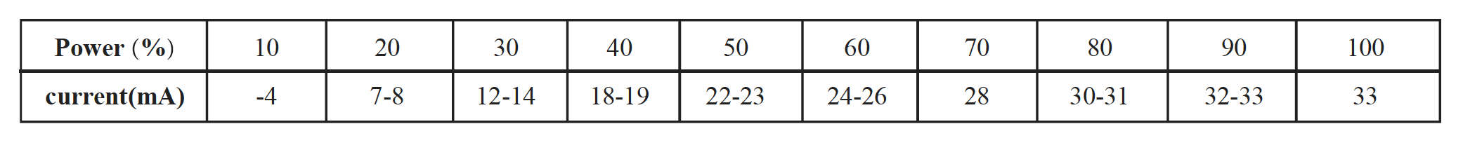
Here’s the current draw for a 130w machine from an OMTech manual.
So does this suggest the pot fine tunes the power range sent over from Lightburn or the control panel rather than total power? I guess this could be useful to fine tune during a job.
As far as the power supply is concerned, it knows nothing of the controller or LightBurn or their power ranges. All it sees is are the Enable and PWM signals, with 99% (or 100%) PWM calling for “full power” from the supply.
The supply’s internal trimpot and the external knob can only adjust the maximum current available at 100% PWM: the PWM signal then scales the current downward from that maximum.
Not much room for mystery there! ![]()
That acts internal to the supply and should fire the laser when the controller plug is removed. We have no way of knowing what current it sets, but with the controller unplugged, the results obviously have nothing to do with setting inside the controller or LightBurn.
From the table, “full power” should happen with 33 mA of tube current.
Set the controller for a two second pulse at 50% PWM, turn the knob all the way up (fully clockwise?) and fire the pulse. While it’s active, the table says the current should be 22-23 mA.
If that’s the case, then you’re done: the PWM value scales the current from zero to the tube’s full power in the obvious way.
If the current is something else, then you can adjust the internal trimpot to set the current to 23 mA at 50% PWM with the knob all the way up, which should set the maximum current to 33 mA.
This topic was automatically closed 30 days after the last reply. New replies are no longer allowed.