Converting Foot Switch from Input to OUTPUT

Hello,

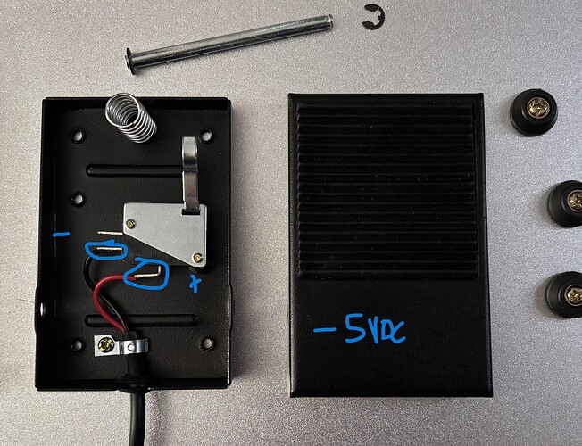
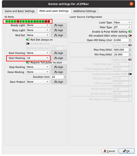
I’d like to have my laser’s exhaust fan relay be triggered to turn ON during jobs and turn OFF after. This should be straight forward, but I am unable to get Port 14 (Foot Pedal) to output. It is always -5VDC relative to ground even when configured for Ready Light, Busy Light, Start Marking, Red Dot, and anything else I thought made sense.

By programming “Ready Light” and other states to Port 14, I thought I would get a positive 5VDC signal on the foot pedal. I understand this is the opposite of what the IO was designed for, but if it’s truly IO, I should be able to make it the O part, not just the I.

I would like to repurpose the foot pedal as an output signal to trigger my exhaust fan relay when jobs are started and turn the relay off when the job is stopped. To me, this makes nothing but sense, but I am not able to output, just input.

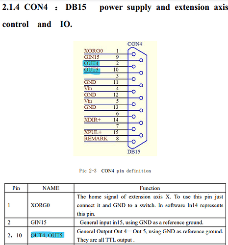
I understand my controller has OUT4 and OUT5 available, but I’d like to avoid soldering directly to the connector or make some other invasive hardware hacks. This solution made the most sense to me.

Can someone help me out with this? This is my first Galvo laser, so I don’t know everything.

Windows 11 PC
Lightburn 1.7.04
CloudRay MP-60 Fiber 60W JPT M7 MOPA
“Updated Controller” LMCV4-FIBER BJJCZ - Closest Manual I could find

Thank you.
This has to be done in the controller source code (and recompiled). An alternative is to use a 5v relay board that has the capability to be set for a HI or LO input energizing the relay.

Thank you Mikey.

I am comfortable with modifying firmware and re-flashing, but I am not seeing anything about end users being able to do this. Do you know how this is done?

I also appreciate your workaround, but the foot pedal output as it is LOW, but it never toggles. In order to use any relay at all, I would need a discrete ON/OFF or HIGH/LOW output from the IO port. If it only has one state, I don’t see how I could run any manner of relay with it.

My other question is what these States in LB are for. If I can’t use “Busy Light” to output a signal to my relay (lying to LB by saying its a light), what do they even do? I have successfully used inputs for my foot pedal and my enclosure’s door switch, but clearly there are hooks in place to toggle lights and red dots. This tells me that LB has control enough of the controller to make it output signals. They are just not working. I am missing something here.

My only alternatives are to use a Hall-effect sensor to detect current passing through wires to trigger my relay or to use a ‘vacuum switch’ like I do for my woodworking equipment. My concern with the vacuum switch is that they all require a minimum activation power of 30W to activate the switch. I have not taken measurements, but I suspect my 60W laser often times will not output 30W.

Thank you for your help. LB folks might not be able to answer due to the holiday, so any help is greatly appreciated.

It’s possible for Free Software firmware, such as found on machines running stock GRBL. Most of the diode lasers run proprietary versions of GRBL; whether they use a fork or just a rip of the basic GRBL code is unknown.

Anything not running GRBL is firmly closed-source and thinly documented, so you get what you get and no changes are possible.

2 Likes

I would bet it is a Ruida controller (I can use some help here). I suspect you will not have access to the source code.

You can’t. I did not think that one thru.

If it is not working, how do you know Lightburn has any control?

What you need is a dedicated laser controller with software to match. Lightburn is not that software. It interfaces with a large variety of controllers and laser machines. Lightburn has some interesting features and capabilities, but I do not think it was ever intended to interface at the hardware level.

I do not have your machine, so I am unable to be a technical resource here. But I do not see where you say what kind of controller you have, And you really need to know that if you expect to interface with it.

That said, I think the Hall sensor is the way to go. Have an Arduino Nano monitor the sensor, which is in the laser power source path. It detects the laser current, turns on the exhaust fan, ignores short dropouts, and has a 30-second delay-off to clear the cabinet of smoke.

I solved the problem on my iCube Pro Max with a rocker switch to control the exhaust fan. Otherwise, the fan ran as long as power was on to the machine. Sometimes, low tech is good enough.

1 Like

I am learning about this machine still, and I’m still trying to get up to speed on lingo. In lightburn, it says its a JCZ Fiber Galvo. I’m assuming JCZ is the proprietary controller, as opposed to GRBL etc. I’m not seeing anything other than that. It seems this is locked down then. Thank you for your input. I’ll consider using a current-sensing relay to run my exhaust system.

Thank you @ednisley

Hey @MikeyH,

You appear to be correct about it being closed-source. The controller is JCZ Fiber Galvo controller which seems to be proprietary. I eventually learned enough to realize this. My diode laser was GRBL, but this one is not open source.

I don’t know enough about Lightburn Galvo function to know if it’s a software limitation or my own ignorance. I was hoping a LB Staff Member would help out. I searched the wiki/docs but nothing about using outputs is mentioned in the digital IO section.

I linked the manual for the controller board, but you may have been waiting for me to say it’s a JCZ controller which I just realized. Pardon my ignorance, when I hear controller, I focus on hardware ( I’m an embedded engineer, guilty as charged :laughing:).

Given what I’ve just come to realize, it seems this is my best bet.

I really appreciate the help. I would still like to see what a LightBurn pro has to say about these “States” I can program for each IO. The way these options are presented is that they can control the controller to output, but that doesn’t seem to be the case.

The “States” seem to work for inputs well enough, such as the pedal and my enclosure door, but outputs are a different matter entirely. I still maintain that the hooks appear to be present for outputting. I might also try my hand at hardware hacking my relay to OUT4 or OUT5 which is part of the DB15 connector on my controller. I have the skills to do it, but it’s not a clean solution like my original idea. These pins are available for use, but the wires need to be soldered inside the head of the DB15 connector. If I pull this off, Ill post pictures. I’m just crazy enough to try it.

Thank you for your help.
Tom

@MikeyH it’s a JCZ controller for a fiber laser. Similar to mine…


Swap your meters leads around. These are ttl compatible output, so a negative voltage would damage these ports.

Add to that, there is no negative supply, so outputting a negative value isn’t very easy to come by.

You might be thinking of things like your foot switch, completes the circuit to ground.

This is documented your supplied pdf.

The Ruida has them and they are pre-programmed, as far as I can tell. They also warn you they are reserved to Ruida. I’d be surprised if it’s something really usable or we’d have them them used in the last 3 years, somewhere…


As @ednisley states, this doesn’t run grbl.


There is no firmware I’ve ever seen available, doesn’t mean is doesn’t exits, but I have no idea where it is and how you’d load it onto the controller. I’ve never seen anything on re-configuring outputs, it’s pretty likely they’re outputting something. Use your voltmeter, it should be a ttl as defined in your documentation.

I doubt Lightburn knows all there is about this controller. It’s of Chinese origin, meaning we have pretty much what’s in the document you posted states. I have a more detailed manual on your JPT source.

They are indicated as outputs, but I don’t know what it’s configured to output. My guess is it already outputs something, but haven’t seen anything on that either. I also doubt Lightburn knows if it’s configurable or not…

Only one of the Lightburn people can answer that detailed information about what they know about the controller… We can ask @gilaraujo, maybe he knows or can route this to someone who does.

IMHO, I doubt the knowledge is there, but no harm in asking.

Good luck

:smile_cat:

1 Like

Thank you @jkwilborn for your helpful response.

I agree that -5VDC is rare to see. It seems you are correct about there not being any negative voltage output from the laser components. If I were to swap my DMM leads, my positive would be on Black and Negative on Red (talking about foot pedal leads), but seeing as how this is a single pole switch, polarity/wire color doesn’t matter, and the factory knows it. The negative voltage isn’t necessarily hitting the port, I bet these wires are just agnostic even though they are colored a way we are used to seeing. That was a good lesson in objectivity.

This is core info that I’m searching for (I have not seen these warnings :face_with_open_eyes_and_hand_over_mouth:. So LB is designed for so many controllers. I am seeing the options, but they don’t specify which options are for which controller, so it is entirely possible that the options I am questioning are just for other controllers. Seems like if I specify my controller, LB would automatically filter out features that are not on my controller (just a thought, maybe I’m wrong [maybe a future feature request?]).

Thank you for linking this. I am more interested in the controller/“brains” than the power source but this also has interesting info about which pins contribute power, which could help me. Thanks.

Summon the Wizards! I am willing to experiment and provide info + feedback if needed.

Your response was particularly technical and helpful. I’m very grateful for you chiming in.
Tom

Been there, done that:

Definitely violated the Principle of Least Surprise.

:grin:

2 Likes

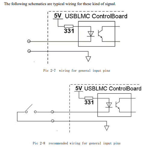
THe manual you supplied states very clearly that the inputs only complete a circuit for the 5V to turn on the emitter of an optical isolator. The bottom shows how the foot switch is used.

It also states the outputs are ttl and that driving them externally will damage them.

JCZ, as far as I know doesn’t give Lightburn any information, it if did they’d be up operating on the hardware that run EZCad3. These Chinese companies are like that. Like there are no schematics.

I’d wait for one of the Lightburn people to address this, if anyone knows, it is they.

Just posted the source manual so you’d have it, not that it’s related other than control interface.

:smile_cat:

1 Like