I am using a Monport GM 60 watt laser and had currently been using a 175 x 175 lens. I just installed a 300 x 300 lens and am having issues getting it set up.
I’ve done the 9 point correction MANY times and I’ve even reinstalled both the Seacad config and the lmcpar config but my files don’t have a markcfg7. I’m not that good with the manual calibration (even though I’ve tried many many times to do it). Does anyone know how to get a markcfg7 file so I can import the settings for the 300 x 300 lens.
I replied to your other post. From looking your settings you are not doing something right with the 9 point correction. The Markcfg7 file is supplied by the laser manufacturer, lens and machine specific. Has to be done at the factory.
I like to use the wide black painters tape for configuring lenses. Get a nice crisp white line with low power. Also, with my 300x300, have to go a lot less then the recommended % on the 2nd screen. Maybe 60%? 70%? IIFC.
Thank you for your reply. We’ve decided to go back to the 175 x 175 lens until we learn the machine more. So, I’m resetting everything back. My main issue is I’m not finding any files listed as markcfg7 on the thumbdrive Monport sent with the machine. Monport uses seacad vs ezcad so could it be listed under something else? I’ve reached out to Monport and asked but so far no one has gotten back to me.
If your machine uses SeaCad/BSL, you won’t find a markcfg7 file in the installation folder.
Look for either a BslCAD.cfg or LmcPar.cfg file, usually in the ‘config’ subfolder.
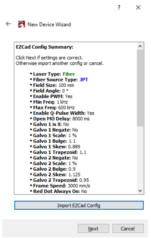
If you import the correct config file, you should see a summary similar to this:
After you added the device with the correct settings, see if you received a .COR file in the folder. That’s a Lens Correction file that you can load in “Edit > Device Settings”.
There would be one for each lens.
Thank you. Yes. I do have both of those files. Do I install them both?
I do see a sea.cor file. I installed that where it says load COR file but it doesn’t seem to do anything.
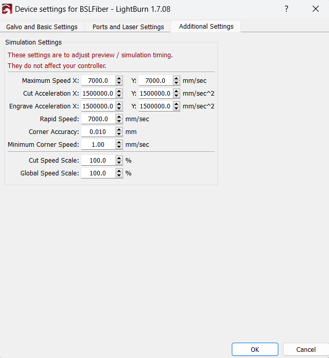
Can you send us both .cfg files and screenshots of both tabs in the Device Settings?
Sometimes, one of the config files only holds some parameters, while the other file holds timing values for the laser.
With this filename, we can’t know which lens it’s made for. Is it in a subfolder named more cleverly?
You should see a difference when you test by framing a rectrangle of a known size. (No need to engrave it, just try to measure the distance of the red laser frame and look for bulged lines.
Yes. I will in a second. I’m actually uninstalling both lightburn and the laser and reinstalling in case I did something wrong. Quick question, do I need to also put in the parameters and info in the MPLaser if I don’t plan on using it. I only want to use Lightburn with the laser. Thanks
Okay. I did the resetting of it vs installing. I’ve got all the settings imported into lightburn. I haven’t done the 9 point correction yet though. I want to make sure all of these are correct first. I’ll upload the snapshots I’ve taken. Thanks
I did a test run. Sometimes the frame works right away, other times I have to try it a few times before it shows anything. Also, when it first starts engraving it has a strong laser beam and digs in deep, but right away (literally after the first second) the beam dies down to where it is doing more of a marking vs an engraving. I have the same parameters that I used before and have done several gun slides with it and it worked well. Any suggestions as to why it’s doing this? Thanks
We can’t see the first part of the summary of the import but it looks quite complete. I’m guessing, this was the LmcPar.cfg?
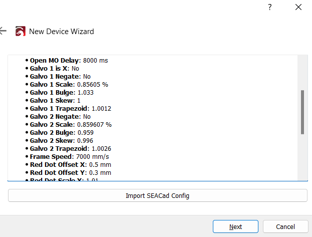
The other screenshot of the summary showing the Jump Delays and Timings is then probably the BslCAD.cfg. It’s not currently possible to load both files in LightBurn (We are working to change this) - Did you manually enter them in the Device Settings or were they included in the other config file?
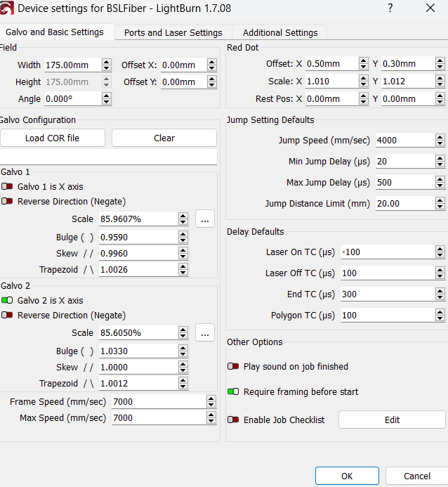
Before you do the 9-Point Calibration, engrave a rectangle of 150x150mm and measure the result. - The config file you loaded already populated the Scale, Bulge, Skew and Trapezoid values, and you might not even need to calibrate the lens.
“Try a few times”, meaning pressing “Frame” again or restart the laser? If you press frame and it doesn’t start right away, what status message do you see in the Laser window?
That’s expected! After some passes, the focal distance changes. Lowering the Z-Axis should help.
If “literally after the first second” it is not a focus issue. A 175x175 would take a lot of passes to get very far out of focus. Something else going on. Is it one complete pass, less then one pass, or after more then one pass?
While I can’t comment to specifics, I was able to setup our 300x300 lens on our HL-YEAH laser with good results. I used the 9 point method to get close and then tweaked settings (one by one) to get the scale, skew and bilge dialed in.
For me a large sheet of aluminum or galvanized and a fat Sharpie marker are another good alternative to the painters tape. You only need to use Sharpie at the intersections which can be seen when framing. It allows for easy iterations as you can cover up with fresh ink and no new tape. It also cleans up easy with IPA.
This allows you to extend the marking surface to get as big of a grid as possible since the larger the 9 point grid is, the less error there is. A large set of calipers or rule with low profile to reduce parallax is ideal as well. Putting the ruler on edge instead of flat can sometimes help minimize errors in reading.
It is a pain but can yield a good calibration. Perhaps in the future we can get a 25 point calibration process to help with this. Regardless, I’ll take an annoying few hours of the 9 point and adjustments over using EZCad any day.