Could anyone help with the calls?
I’ve already tried to see the ones in the group here and nothing works.
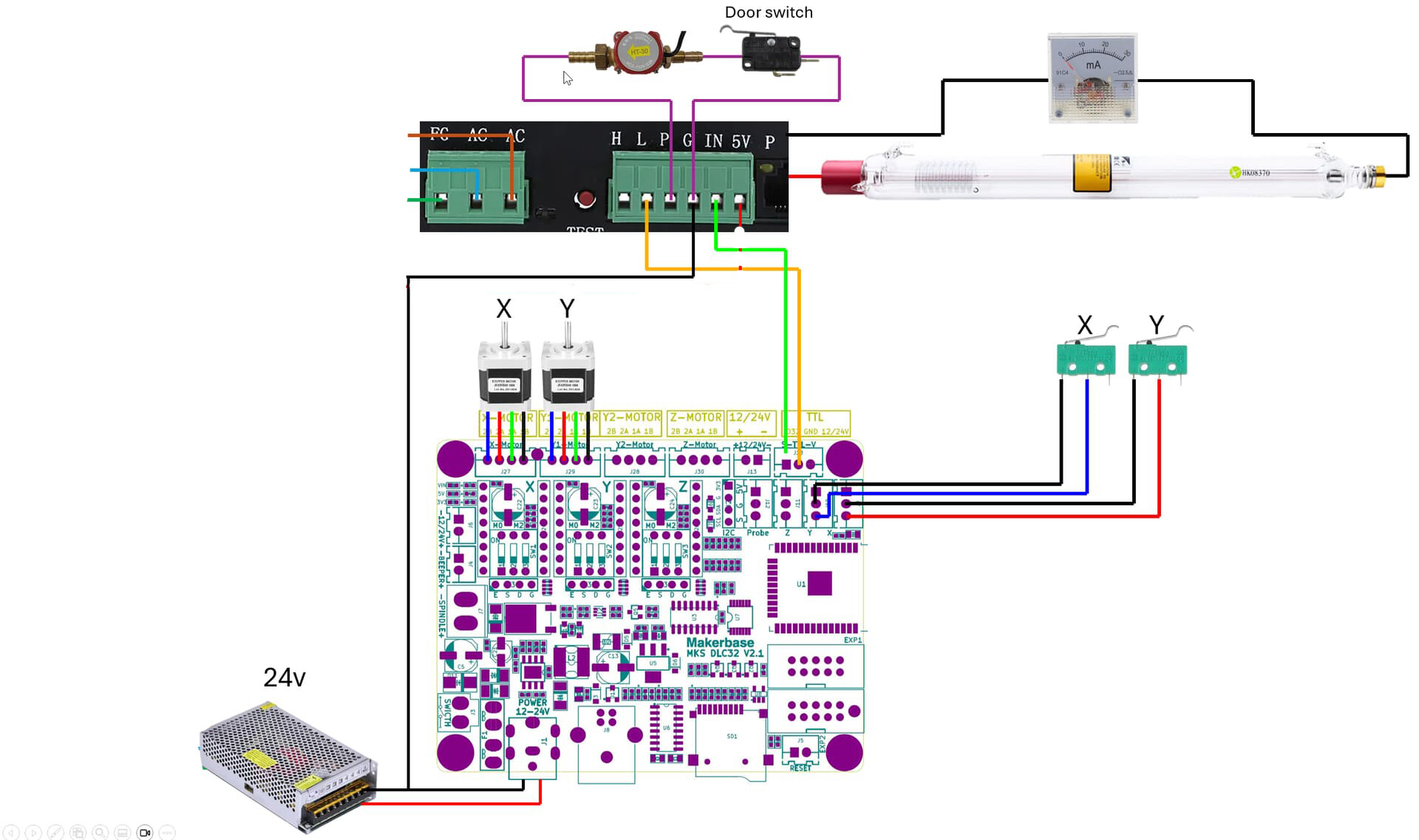
If anyone here can take the image and make the connections using a paint drawing, I would appreciate it. I’ve done so many that I’m afraid of burning the machine/plate.
I don’t understand anything about electronics and I’m afraid of damaging something.
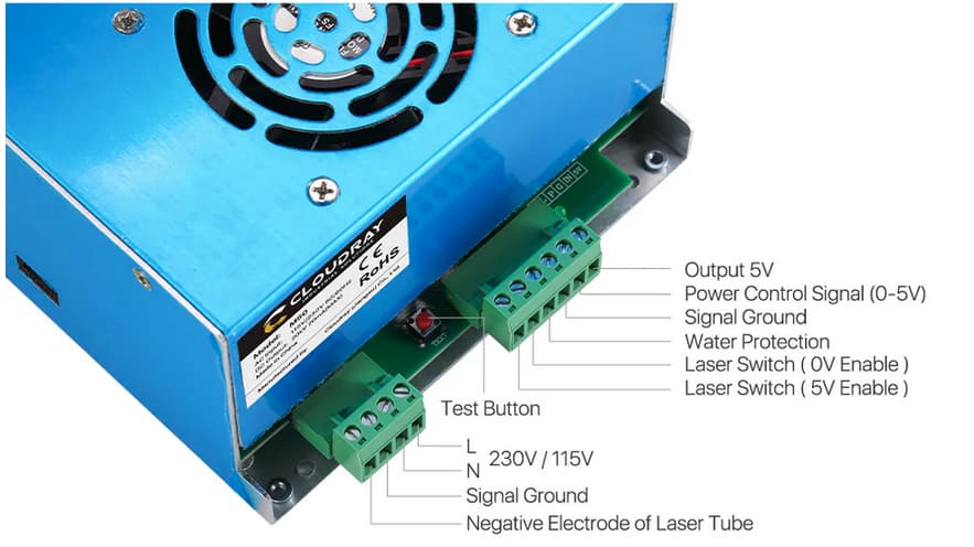
You’re likely not going to have a water protect output on your control boad, so you’d have to wire this to your sensor or ground. If you ground it, there is no way to protect the machine from you running with the circulating pump disabled.
Upper right of the control board is the pwm output, you only need the signal, although you can use this as a signal ground also.
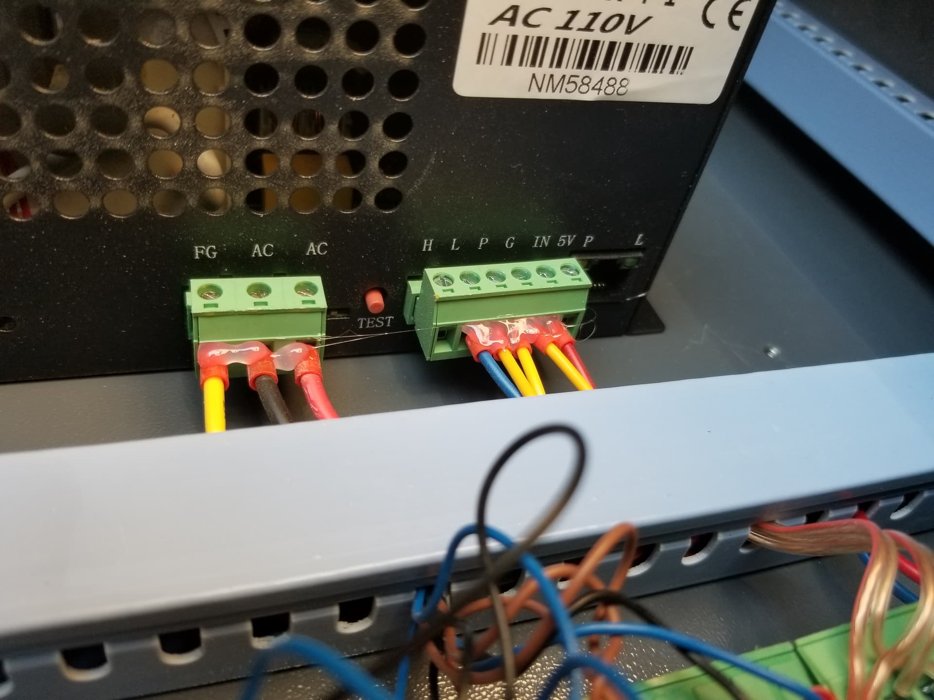
The negative electrode return is used as a cathode (negative) connection for the tube. Most of us wire these to ground however you want to do it. FG is field ground and should work. I suspect in your photo, the blue wire is just a jumper to neutral.
The HV supplies on my shelf (similar to the M60) all arrived with a pigtail lead for the cathode connection and no separate Negative electrode of laser tube terminal (as in the MYJG50W), so I’m extrapolating a bit.
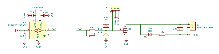
From what I can make out of the circuitry, the laser tube cathode connection goes through a current sensing resistor on the PCB, so it should not go directly to the FG / frame ground terminal. What the circuitry inside does remains a mystery.
The FG terminal should be wired to the machine frame to ensure the power supply case has a solid safety ground connection. In principle the mounting screws should do that, but …
Good evening.
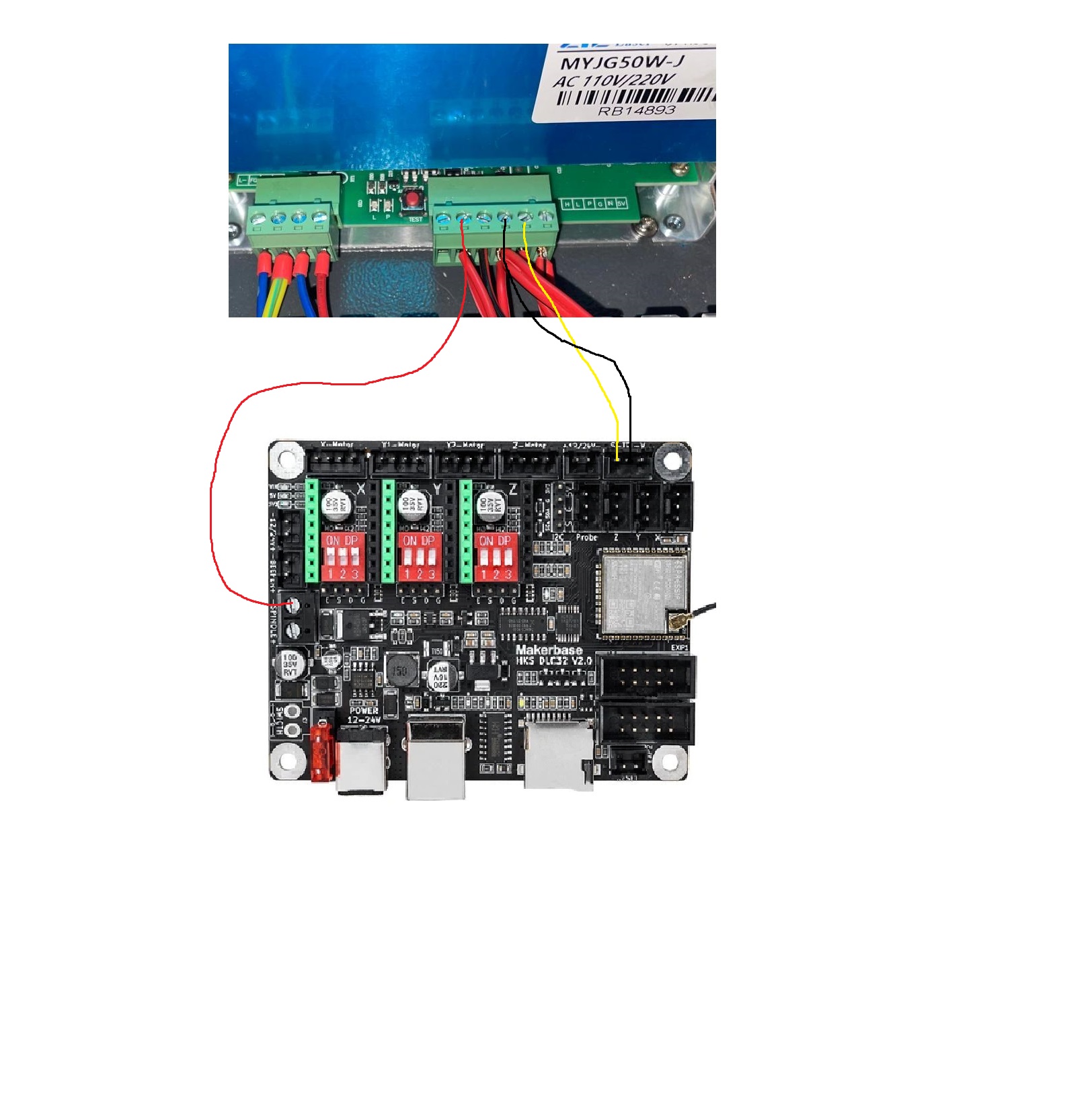
I made this connection as shown in the image.
It cuts and makes lines, but does not engrave.
The laser does not fire anything that engraves.
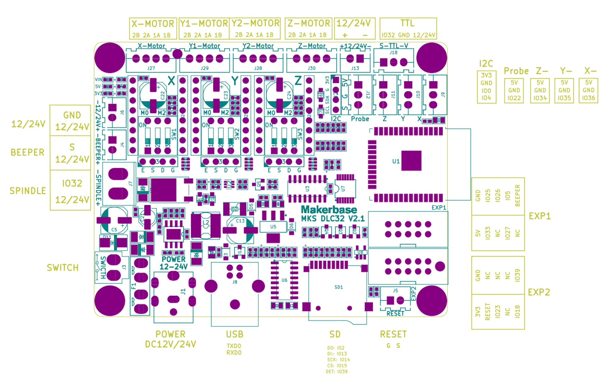
I suspect you have the same issue that I have. I believe your issue is that your minimum power is set too low during M4 operations. I’m running firmware 2.10 on my MKS DLC32 controller. It’s ignoring my $31 settings.
Assuming your $30=1000,
Try: $31=150
That sets the min power to 15%. If it does make a difference, your need to adjust it to your real min power.
Then see if it makes a difference. Maybe whatever firmware version you have on your board honors that setting. My version appears to ignore that setting. What firmware version are you using?
The spindle output should not be used here. It’s just an inverted pwm signal and isn’t driving the tube properly. When I had mine on the co2, I wired the L signal through a manual switch to ground. It was laser enable. In the drawing.
P should be run to a coolant switch to ground. When coolant is flowing, it pulls P low.
With L low, it will lase at whatever current the IN terminal has applied.
So you wouldn’t want low power to be set to 15%, it needs to turn off completely. $31 should be zero.
Mines grounded from the cathode lead of the mA meter mount ground at the meter, same as chassis ground.
Going through any kind of resistor here would not be of any help, unless their voltmeter was across it… it reads current, the current is the same through both circuits, resistance or not.
NO, not with a tube laser. The min spec for $31 sets the power floor. The PWM signal drops to 0V during G0 moves. That pull to 0V disables the laser. Under G1 codes, the power floor is set by $31 and MUST be correctly set for M4 to correctly function. Otherwise, you’ll have inconsistent laser output. This doesn’t apply to solid state lasers. I believe the OP is using a CO2 laser, which does need this. This is known/documented.
To further make this harder for the OP, I suspect his firmware will ignore anything he sets $31. Hopefully they can report back soon.
The resistor is inside the power supply for the usual M60 / ZYE boxes, where (I think) the supply’s control circuitry reads the developed voltage.
Perhaps the internal resistor develops a voltage for the remote current display intended to plug into the not-a-network jack on those supplies. That would explain why your supply is perfectly happy running without having the tube current going into that terminal.
Given the wild-and-wooly variety of clone / knockoff supplies, who knows? I’d wire it up according to whatever doc might have come with it, which surely shows the tube’s cathode lead should ultimately go to the appropriate terminal.
Using the center of the connector, is ground. So in effect you’re turning on the lps. I don’t think this is the best way as you could be in there and the pwm would turn on the laser.
I wired L through as switch to ground, for a manual laser enable.