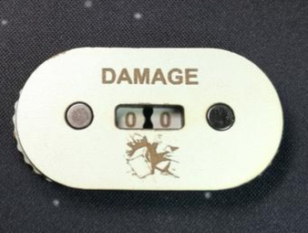
Evening Folks, turns out I wasted the time of Bruce and Oz with my last question. It wasnt what I was after. Stuffed around with it for ages till I realised this is not at all what I wanted.
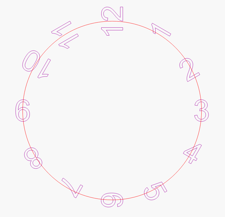
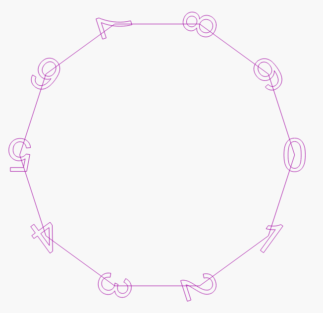
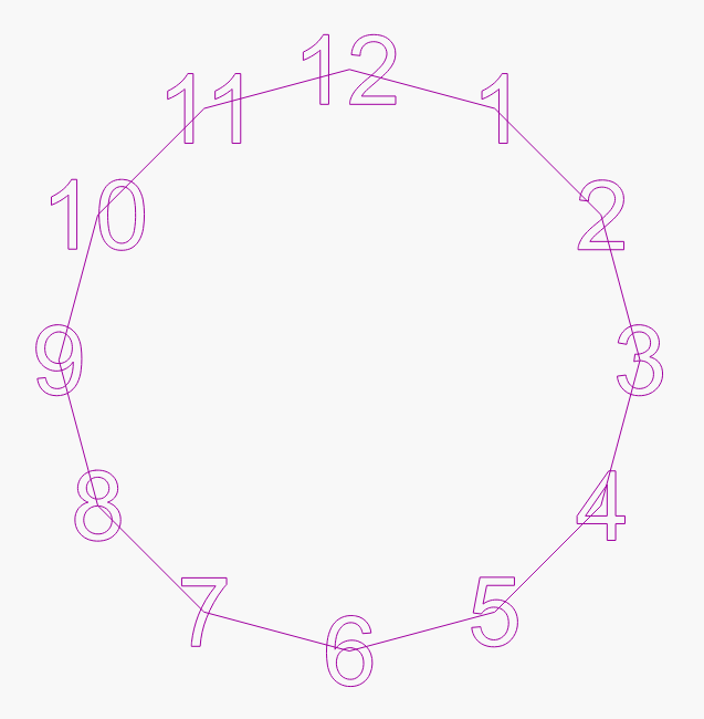
As you see, the counter has numbers that will always orient so that you can see the vertical number as the dial spins. Does anyone have an idea of how to get this to work?
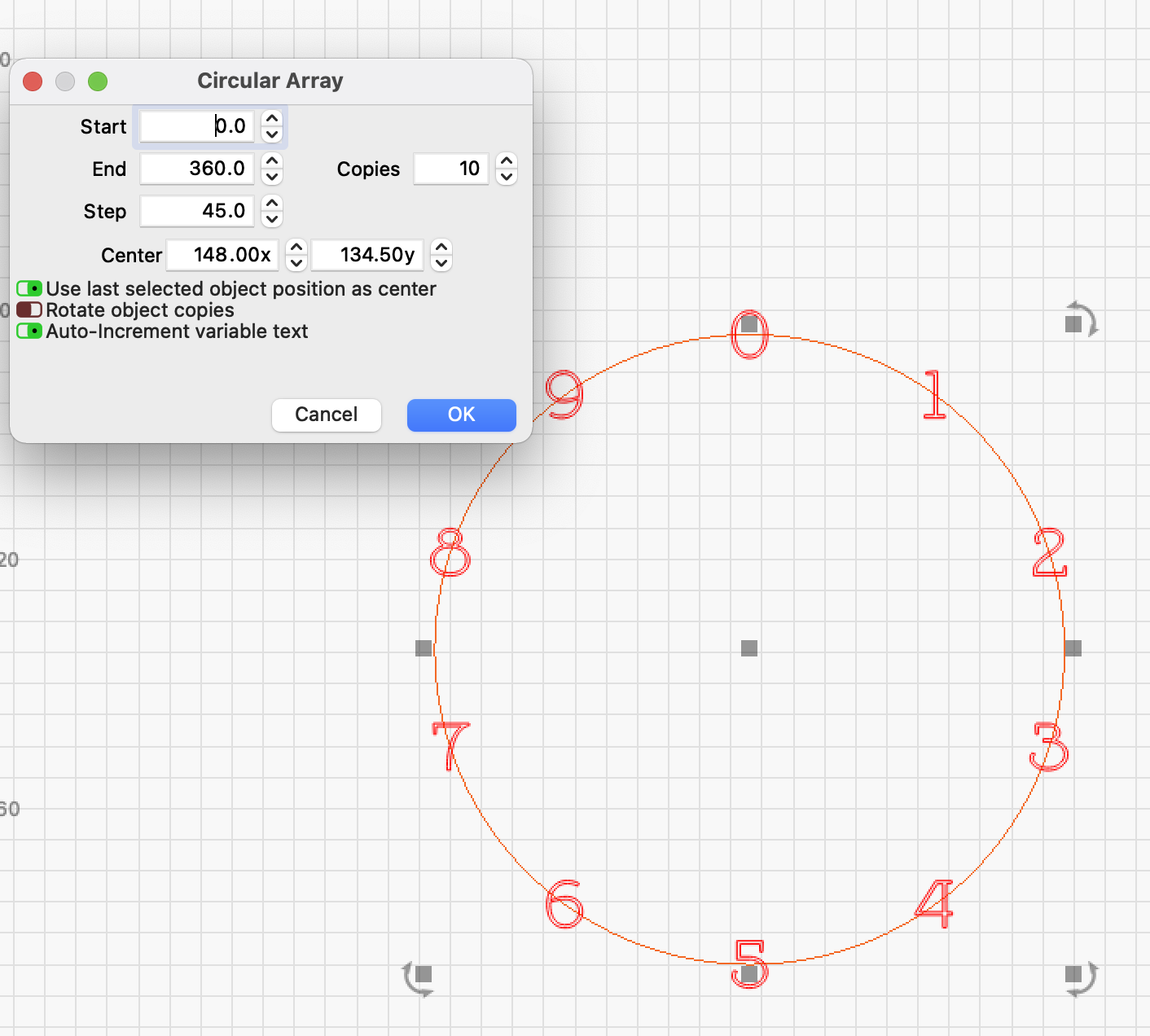
A quick and a bit primitive way I have chosen. You could also make a small variable text with “0-10” and refer to the file, but for such a small task it is a bit overkill.
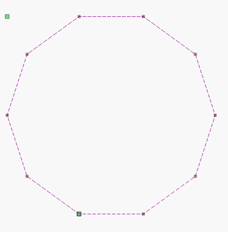
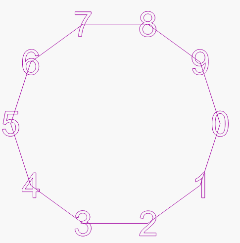
1 draw a circle
2 position a number
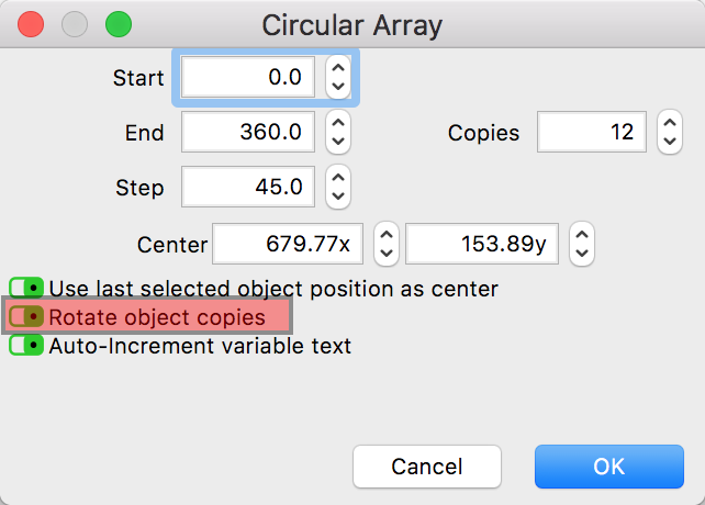
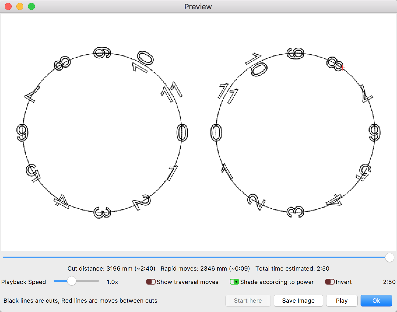
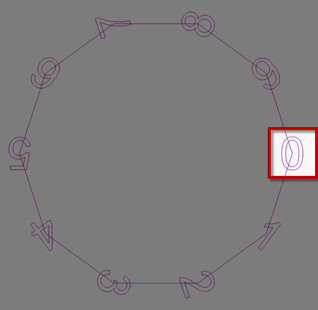
3 Circular Array (see photo)
4 edit text (9 times
5 customize the format
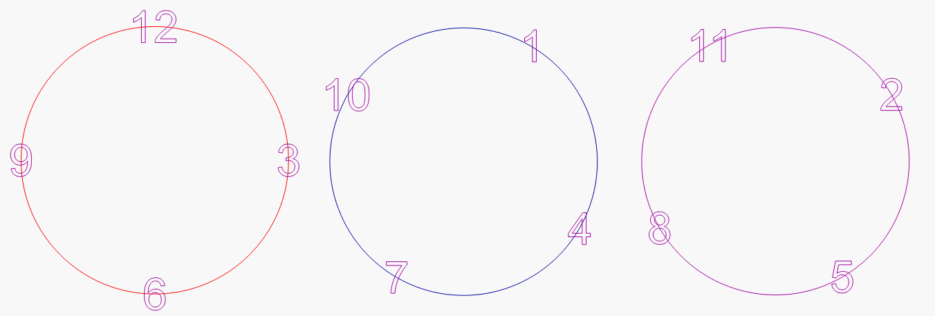
Consider 12 positions on the clock. A full rotation is 360°. 360 / 12 = 30° of rotation for each position that you wish to present in the window of view.
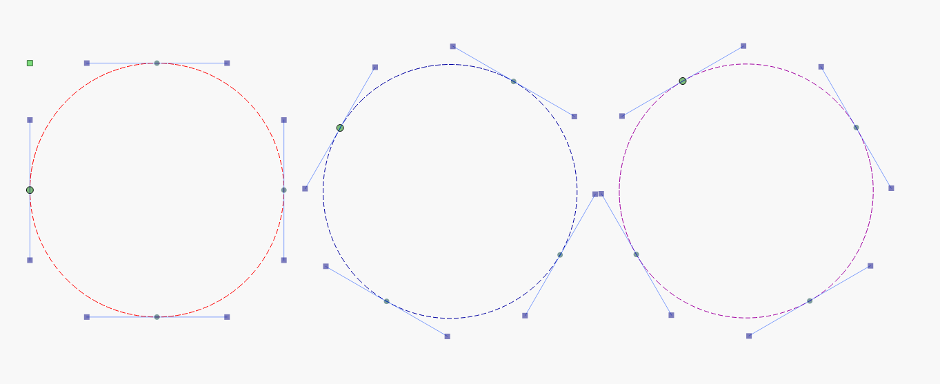
-=For the Left Dial=-
Draw three circles. Rotate one of them 30° and another 60°:
And so now you figured out that in the first example, if you ever want to make a clock face you could just make a 12 sided polygon and place your numbers evenly distributed by snapping them to the nodes.
Maybe I am missing something and thanks for the great detailed explanations, but rotation of objects created during the array build is an included option.
Yes, what you may be overlooking is the challenge in what is needed: a single selected number appearing in the window in the proper orientation on a rotating dial. In your example, the selected number would not be in the proper orientation in the window of the dial. The numbers must be positioned and rotated:
Lookie there! LightBurn always has it built-in! Looks like I am the one overlooking FEATURES
(at least I may have helped others in some way to understand the “old way” we had to figure this stuff out with CAD tricks before fancy feature packed software)
@bernd.dk@Rick@Stroonzo
You guys are fantastic. I am quite the amateur when it comes to most software, if it isnt a game. And never mind that lightburn is great, the community is even better, helping people who have no clue.
I really appreciate the help everyone, thankyou.