I’m using lightburn on a Creality Ender 3 S1 with 5W Laser module.
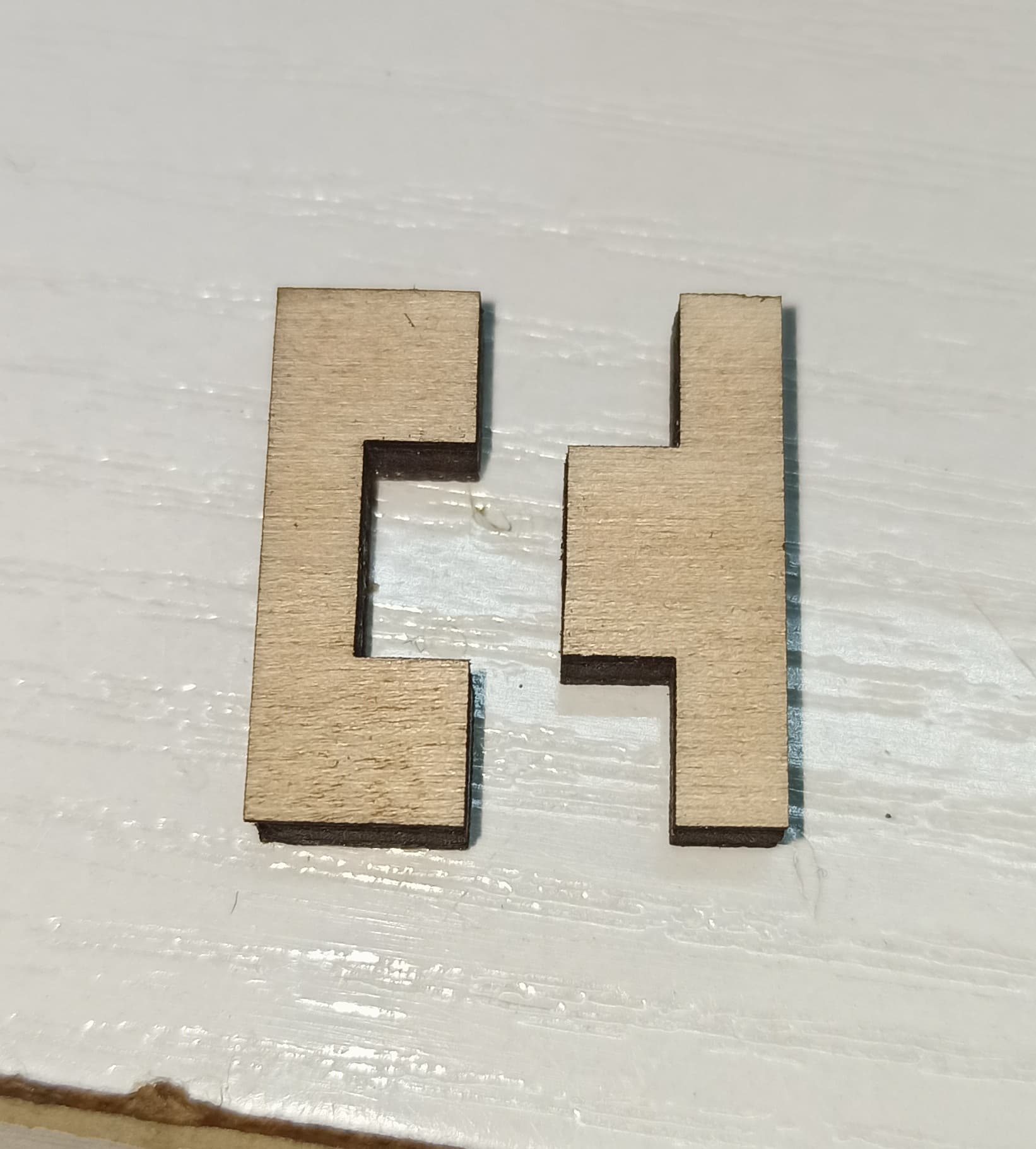
The issue is that I’m getting some weird gcode lines that are not in the job. I have an example of the latest cut. I’m making test cuts to figure out the gap in the finger joint of a box. The drawing is the jod and the photo is the actual cut.
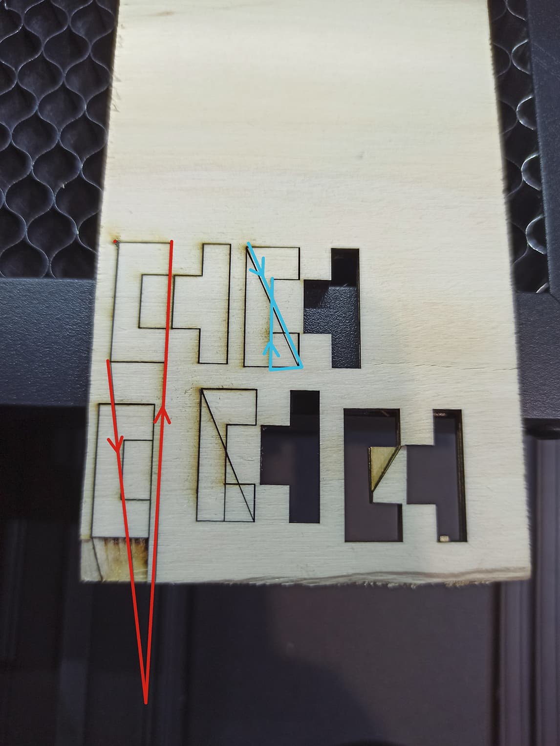
The wrong lines are different in seperate test cuts. I have hightlighted the travel for easy understanding.
Yeah. The g-code doesn’t seem fundamentally broken. This means that your controller is likely not turning off the laser during traversal moves.
For Marlin controllers this is most typically due to incorrect Laser Control Commands being used or due to a firmware configuration issue.
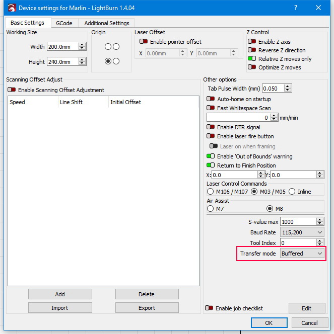
Test the other Laser Control Command options in Edit->Device Settings. Inline is preferable if it works.
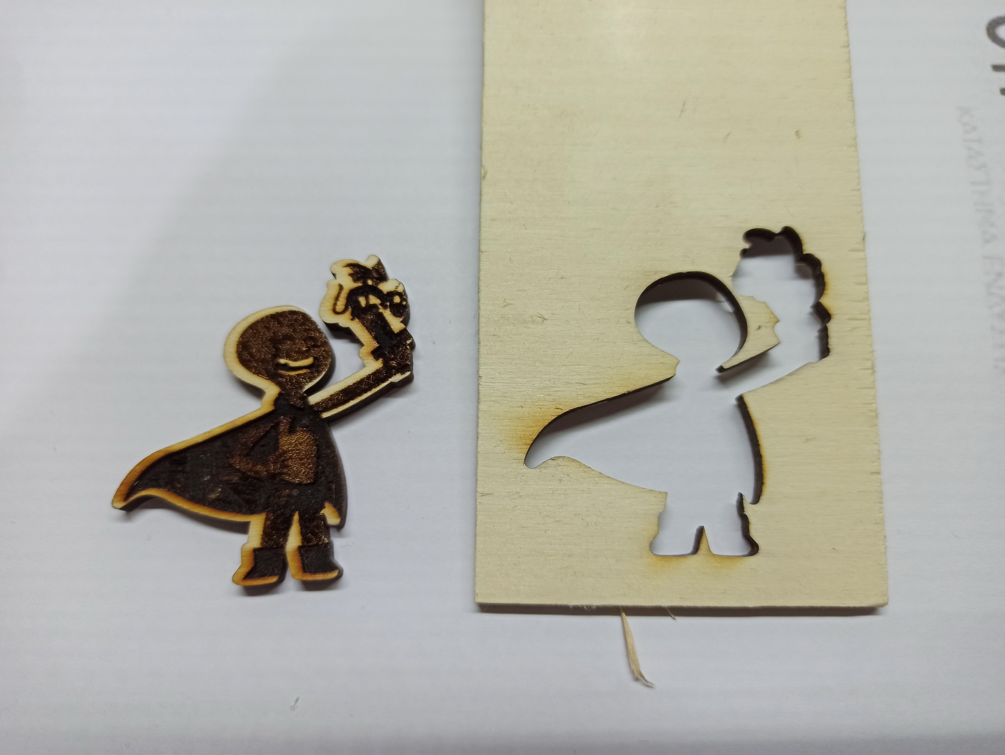
The reason why your test burn works is because it’s a single continuous line for the outline. It looks like you may have the same issue with the fill portion but hard to say without knowing the design.
I tested the other options but although the laser did not turn on for cutting, I spotted wrong travel as well.
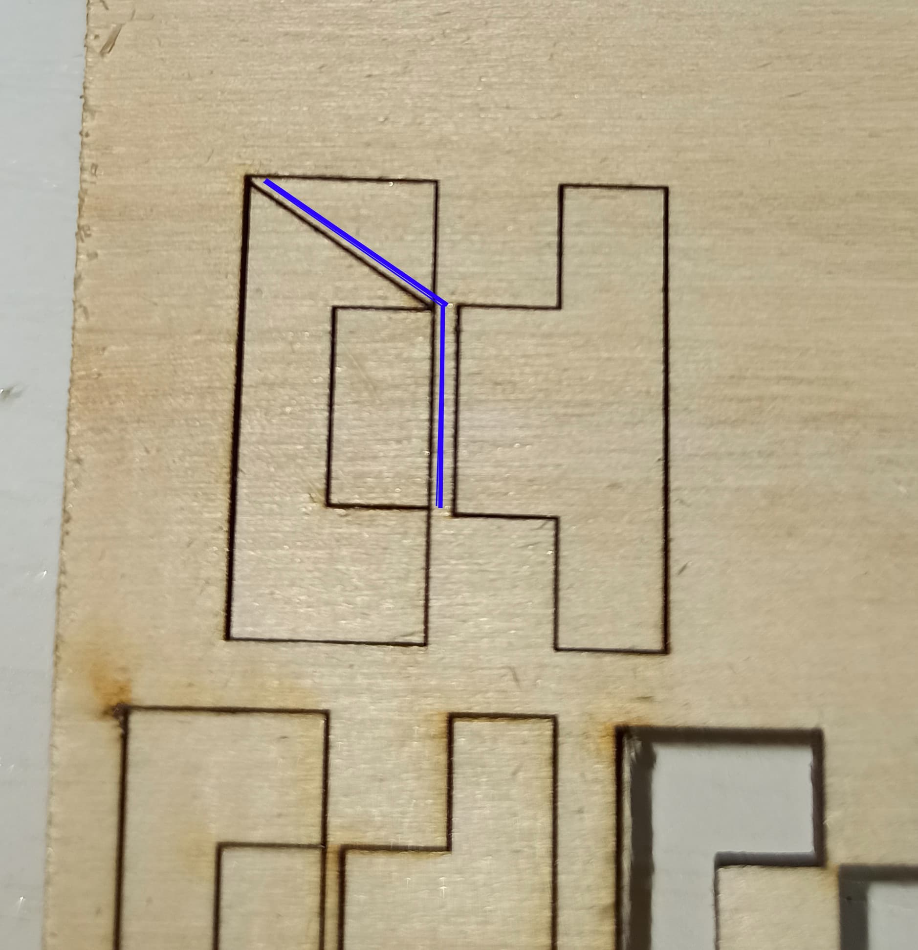
As for the line for the “little guy” is continuous but so is the drawing I’m trying to cut right now. In one case it goes outside off the drawing (red line) and in the other case is seems like skipping lines of the code (cyan line).
If I load the code via card instead of live connection with lightburn would it make any difference?
The drawing is a simple finger joint. Every pair was a single run. In this wood piece you see 5 individual attemps. The problem is that although the job is only the perimeter of the two parts, the red and cyan lines in the photo are wrong travel. The beam is on because it is supposed to run the perimeter but it deflects from the actual drawing.
Firmware is 3.0.4_C and it is the official firmware from Creality. I just spotted a new release to 3.2.0
Let me revise my previous statement about running from SD Card. I think it’s worth a shot. This looks like it could be a communication issue. In that case going to SD Card could indeed resolve it.
If that proves to be the case then just a matter of sorting out the comms issue.
The gcode had a different structure compared to the one generated with the native program of the printer and although it started with the first couple of lines, it then stopped with a message that the consumable has depleted. Since, live connection is working, it is way better and more convenient.
I was messing with those settings in the beginning. The configuration I have is the one that works with this particular machine.
The fact that S value is 255 and Baud 250.000 are typical for Marlin is the first problem I encountered to make it work in the first place.
Finally, I can say it works fine.
Why do you suggest trying other settings in order to switch back to buffered? Is there any significant benefit?
Thank you very much for your knowledge. Since this settings configuration works for me now, I will stick to this but I will try to find if there is another possible configuration that will allow returning to buffered.
The code below is from creality’s software for the laser. As you see, the value for 100% is 1000.
My usage is for hobby and my work area is fairly small (220*220) so I don’t know how complicated of a design will I ever need to cut. But I will surely have your words in mind
This is interesting. They seem to be using “Inline” which helps with performance. As I recall this didn’t work for you so may be due to slightly different syntax expected.
But good to know that it’s compiled into the firmware.
It won’t be about size so much as information density. For example, try burning a grayscale image. That will be about the most demanding job your laser will face from an information density perspective. How does it work?