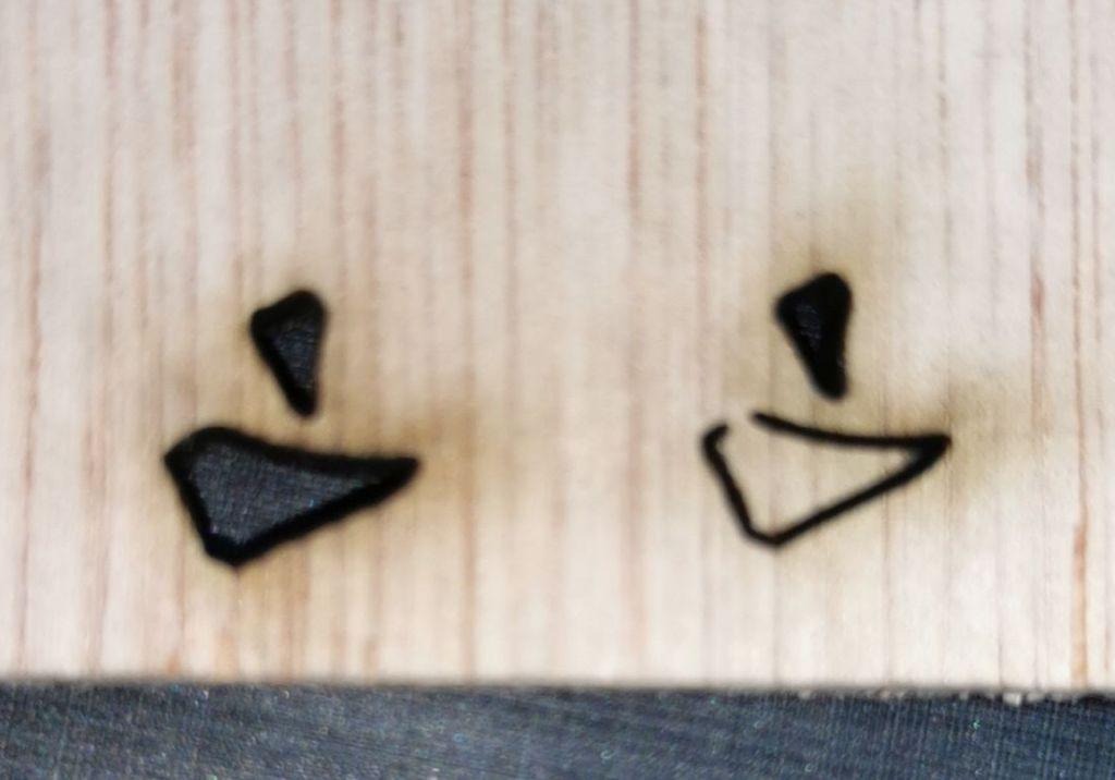
Guess what is the difference ? (Speed, power are then same, wood, geometry. There is 10mm between the two cut start maybe)
The ONLY difference is when I start the cut with job origin on Top Right, it is OK. But when I start bottom left, a small piece of cardboard or wood is NOT cutted. Some other job origin works, some others does not. I did not test everything !
What settings are you using? (Min Power and Max Power, specifically) Do you have tabs enabled? Does it improve at all if you use the ‘Hide Backlash’ option in the ‘Optimization Settings’?
I’m in office now, I’ll check this tonight.
I have installed Lightburn one week ago, and did not change any default, except:
Speed/Power for layer C00
Work origin (Bottom left instead of top right)
Mechanic, belt, optic are perfect.
No tabs enabled of course. This is EXACTLY the same job, exception made to the starting point of the job…
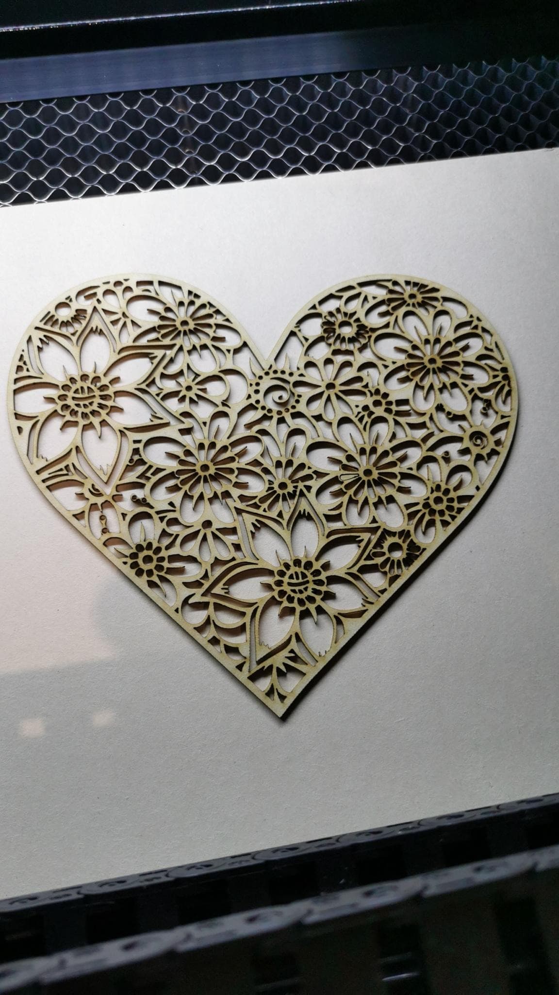
I don’t even move the gantry, I move the piece of wood under the laser each time. I was lucky to catch this issue. Problem came firstly from a very complex cut: Some piece were not able to detach, and I did not understand why. Here is the initial design
I do not see anywhere in my reply that suggests I thought it was random.
Backlash could easily be the issue - when the job is run from different starting points, the path planning in LightBurn chooses different shapes to run, because they are closer to that starting point, and the order of the shapes that follow will be different as well. The shape order and cutting directions affect belt tension when starting and ending a shape.
If you enable the ‘Hide Backlash’ option, it accounts for this, and forces the entry and exit directions of closed shapes to be consistent. If enabling the ‘Hide Backlash’ option makes it run the same from all starting points, then you might have a small amount of looseness or slop in your motion system.
This is what I say after many try. 100% reproductibility for both scenario.
Remember that drawing is extremely small. Then belt problem should be none. And this is the case. Mechanics and optics are perfect.
I will try the same dxf with RDWorks and I ll see what will happen or maybe older release of LB if I got some time.
Complex models (Heart) with many intricated details lead to some piece of material that does not detach properly.
I will try to cut the heart with starting Top right. If everything is perfect, I will conclude that is really not coming from the machine itself or from the parameters, but rather some kind of SW issue.
I have no problem using top right starting point, but it doesn’t make me confident about Lightburn for more complex project.
I honestly think that there is something nasty behind this behavior.
Hello,
yesterday evening, I have cut the heart again on cardboard, starting bottom left and again top right.
Bottom left, came out quite well, but lots (30% maybe) were a little bit difficult to remove. I had to use a needle to remove the attached part.
Then I started again the same cut, (Top Right) and it came out absolutely perfectly. All small pieces remains on the honeycomb, very nice
I took again the extract of the project. Started two time (Bottom left and top right), by moving the cardboard, not the gantry.
I have changed the power just to engrave (Slow speed, Very low power, limit of the laser 8/9%)
You have Power Min set to 0 - that’s almost certainly why this is happening. Power Min is basically the power used for corners, starting, and stopping. Where the laser begins the job from will determine the order and direction of many of the moves, causing it to slow down or stop in different places.
When the laser slows to 10mm/sec or less, it will drop the power to 0 because that is what you have told it to do. CO2 lasers don’t fire below a minimum power threshold, usually about 10% of the tube wattage. if you are cutting, you should set Power Max and Power Min to the same value, or very close to it.
This is absolutely right.
My LB profiles are not very tuned right now (Fresh install).
I will correct the min value for the Laser and check the results.
But even if it correct the problem, the current results are not consistent
when I start Top right or bottom left.
I would have been happier if both cut would have failed…
On my side, I will try this fix, but could you tell me why both results are not consistent ? (Only parameter which has changed is start of work)
OK, I admit that the setting for Min Power (0%) are not correct (Even if it works absolutely perfectly, but only starting Top Right)
It’s not a big issue maybe, but I still don’t understand why the results are not consistent.
It could be some kind of nasty bug that hide something worse, but my 30+ years as a professionnal SW Dev don’t allow me to see the faulty lines of codes through the (beautiful) LB interface !
I think the difference may be due to the direction the beam travels around the shape, because that affects the path planning and the speed along the path.
Traveling clockwise, the path finishes on the straight line. Lines are produced by a single command, with the acceleration settings controlling the speed and, therefore, the beam power along the line. With the minimum power set to zero, the beam shuts off as the speed decreases.
Traveling counterclockwise, the path ends on the curved section, made up of many tiny straight lines. The speed along each lines begins at a specific takeoff speed that is high enough to fire the laser, but, because the line is so short, the acceleration settings have no effect: the line ends before the speed changes. As a result, the beam cuts “normally” for each of the zillion tiny lines along the curve.
Some CNC controllers have the ability to follow Bezier curves with proper acceleration and speed controls along the entire length, but the probability of that path being specified as a Bezier curve and a Ruida controller handling it seems … low.
Given the number of interacting parameters in any CNC machine, getting everything right for every material is an art, not a science!
I build a quite big CNC a couple of years ago, and I felt sometimes frustated before the learning curve was not so straightforward.
It was a science, an art, and sometimes you had to be a strong believer to achieve your goals
But it worked, it was the most important.
Experience and taking some notes to improve reproductivity is a key point…
If I follow your point, I should get opposite results if my mirror my design. Then, Bottom Left should work, but top right should not.
I will try this tonight.
Edinsley did a better job of explaining it, but this is exactly what I was trying to say in the above paragraph.
The direction the laser travels around the various shapes, and how it moves between them, affects where the laser has to stop or slow down, and when your Min Power value is zero, those points will have less cutting power applied.
If the path is traveled in such a way that the direction of the laser head at the end of one shape is the same direction it will take when moving to the next one, the head does not need to make a full stop, so the power would not be ramped down to Min Power.
If the direction to the next shape is the opposite direction to how the laser is traveling when it finishes the current shape, it would have to stop completely to change direction to travel to the next shape, and that full stop would cause power to ramp down to Min Power.
The starting point of your job will determine how the laser head travels through the various shapes, so this can absolutely affect where and when the laser head needs to stop.