I thought it was working correctly the last project but now I’m thinking it was probably off I just couldn’t see it. Every time it tries to home I assume it’s trying to go to X0,Y0 which I would think is the front most left corner. But once it gets to the corner the motor keeps trying to go to the left I think it makes a grinding sound. I’ll have to figure out how to export the lightburn file
You can start a reply, then drag-n-drop the LightBurn file onto the editor and away it goes!
That’s definitely not what it should be doing. Let’s work on fixing that problem first, which may simplify the other problems.
@berainlb has encyclopedic knowledge of desktop laser homing problems, so … more eyes will help.
JK LOGOS.lbrn2 (41.4 KB)
I’ve reviewed the Topic and feel like this deserves some back to basics.
A few questions:
- Where are the limit switches located for homing. I believe this machine is intended to machine back-right but sounds like homing directs laser head to front-left. Please confirm.
- Do jogging controls work as intended? Meaning left moves left, right moves right, up moves up, and downs moves down?
- Does the machine burn dimensionally correct? Design a square 100x100 mm. Then burn line and fill versions of this. Measure the resulting squares. How do the measurements compare against design?
- Draw a circle and run in Line mode. Do the ends of the circle connect?
- I’m also noticing a scanning offset. Test this by creating a 100 x 100 mm square filled with a large interval at 1mm. Then burn.
Please post photos of the result. I suggest burning these on known flat surfaces of cheap material like cardboard.
- Homing directs the laser to the front left. I’m not sure where to check for the homing limit switches.
- Jogging controls work perfect.
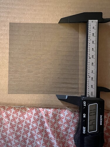
- I burned a 50mm square and used my caliper to measure. It came out correct on both sides.
- The ends of the circle do connect.
I’ll do #5 in a minute.
I have and there’s no play noticeable in either.
I tried grouping the job and it still came out wrong.
Okay you guys so I did a test on two circles within eachother on two different layers. First run I did a fill on the inner layer and line on the outer. Second run I did lines on both layers. The first run my fill layer looks elongated but when I run it as a line it’s a perfect circle?
Examine the machine. Manually move the laser head slowly to left and right extremes of the gantry. If you have mechanical switches you should be able to hear and feel the switch actuate. Repeat for front and back.
You should also be able to follow the connection from the controller box. The limit switches are labeled. Follow the cables all the way to the switches themselves.
This is all good then. This likely means you don’t have a mechanical backlash issue.
The scanning test indicates a problem with a scanning offset. Use the Scanning Offset Adjustment in Edit->Device Settings to correct for this.
However, that filled scan doesn’t look square. Did you also do a filled test at 100x100 mm?
I suspect what’s happening is that somehow you’re having an issue with engravings that’s not showing up with line operations. Not clear to me yet what would cause that.
If you haven’t tried the filled 100x100 mm square, please do so. Will give an indication whether the issue is on the X or Y.
Yea that fill square I did was 100x100mm. It has limit switches that are on the left and right side of the x axis that it hits when it homes. I did notice a wire getting caught
Does that allow you to home now?
Can you do the same test with a more normal interval size, then measure the square? I suspect at least one of the dimensions will be wrong.
I’d suggest first resolving the scanning offset, however.
Yes it allows me to home now. I ran a 100x100mm square and it came out 100x101.4
I’ll have to research into fixing overscan
Okay. Very good. This should allow for repeatability in placement.
Not as bad as I was expecting. Must be perspective but it looked to me that the square was much taller than wide.
The engraved circle in the previous post looked oblong. Is that not the case in person?
Once you sort out the scanning offset we can tackle the initial concern of the Topic.
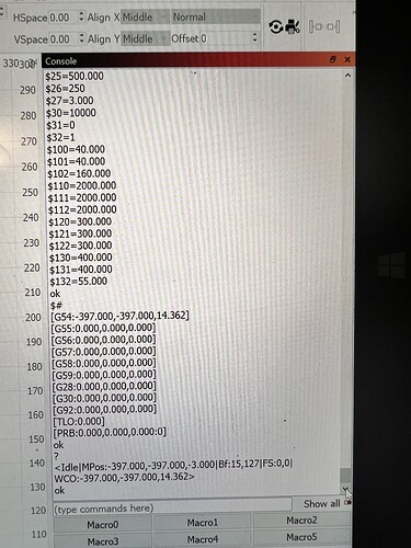
Once scanning offset is well addressed can you run these commands in Console and return output?
$H
$I
$$
$#
?
Looks like you may still have a little bit of room for improvement. See if you can tweak it a bit better. You may want to try a wider range of speeds as well.
The numbers in the last test reveal some other potential issues. Either you are experiencing some mechanical backlash or possibly your laser head is not rigidly attached to the laser mount. Or possibly the laser mount is not rigidly attached to the gantry.
Can you grab the laser head at the bottom and try pushing back and forth? Do you feel a lot of movement there?
Also, looking at the output of the Console commands it looks like you may be missing a setting that will help you with Absolute Coords.
Run this in Console:
$10=0
This will have the controller report working position rather than machine position. This should allow you to use Absolute Coords as the Start From mode without fuss.
Afterward, try running an additional test:
- Create a plus or X shape and place it at a specific location in the workspace
- Set Cut setting to Line at a reasonable speed and power
- Set Start From mode to Absolute Coords
- Burn the shape
- After the job completes, run the job again.
- Do the resulting burns align perfectly?
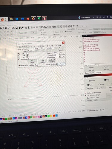
When I try to run absolute coords it puts my start position in the front left corner. Then when it tries to go to start point it hits my Y limit switch and stops
I don’t feel any play in the laser when trying to move it


