Hi everyone, I am new to this, sorry in advance if I am not asking a too stupid question… which I probably am.
I use Windows 10 and I have a Sculpfun S9 engraver, which I am yet to connect to the software. Till I do I have have defined a random engraver in the meanwhile (Cancam) just to be able not to explore the program without being kicked out.
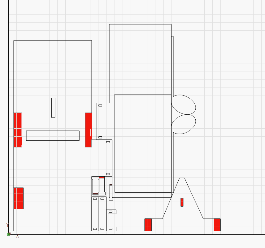
For my project I need to stack multiple DXF files on the same cutting area. Some of these parts are purely geometrical, others also have inner cuts, and others are meant to be engraved/digged out. Some parts have both inner cuts and engravings. I have highlighted in red the parts that I wish to engrave leaving the inner cuts white, using a graphics editor just to make sure I am understood. The question is: how do I define which is a cut and which is an engraving with the software, so that cuts and engravings will run at the same time ?
Thanks in advance - Yehuda Schryer
In LightBurn you can assign specific layers to your lines. In your example, I will give your black lines a red color and determine the parameters to cut with. The areas to be engraved get a different color/layer and, of course, different properties (power and speed). The layers must be arranged in the order in which you have them processed, i.e. the red cutting layer is always the last.
Is this what you are looking for?
I forgot to write that you have to set the program to cut inner shapes first, this is done under optimization setting.
Hi Bernd, thanks a lot for coming back, I really appreciate.
I believe I understood the general idea, but cannot find the right buttons/sequence that will turn lines and areas in different colors. Can you please guide me step by step? (The optimization settings button I did find, though - and yes, it’s set to cut inner lines first).
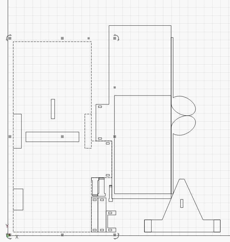
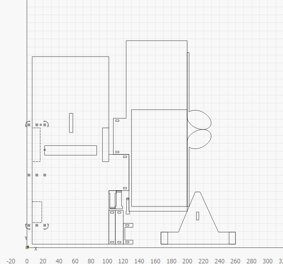
While on the subject I have another problem that I cannot solve: while selecting one of the small rectangular shapes within a bigger shape, the outer line of the shape is activated too, and they won’t ungroup. (first image) Strangely it only happens with that particular shape as there are two other small rectangulars that can be easily ungrouped from the outer lines of the bigger shape. (2nd image)
You’re welcome. It looks as if the one shape on the left side is not “connected” as a shape. In order to rate it, it will be necessary for you to send the lbrn2 file.
When you have a single, coherent shape, or a line or a group, you can assign it to another layer by clicking/selecting it and clicking on a layer color at the bottom. You determine the properties on the right-hand side.
On this page, at the top, there is a link to a very nice online manual, with the very basic steps to start with LightBurn. I’ve used it plus the many videos myself to start with and still occasionally hit up a certain funkrion for a refresher.
I suggest that you look through the manual and I look at your file, then we can talk better together and know what we are talking about.
Let’s get started, just send the file. I will report back in the afternoon.
thanks again here is the file. I have selected the parts I want to engrave and double clicked the # tab. a menu popped out, with 100 speed and 20% power, which I assume should match an engraving (I understand that to get a specific result it should be set by trial and error eventually). But the color I could not change, the color tab did not respond by clicking on it. Surely I a doing something wrong here. So all lines remained black… 1mm new classified.lbrn2 (18.9 KB)
And it’s also not clear to me how do I assign create new numbers in order to perform different tasks: example if I wish to engrave a whole area or to engrave a line.
I will start here. The reason why you cannot ungroup this shape is that one square is “welded” together with the rest of the shape. I don’t know whether it happened when importing the dxf format or is an error in the drawing. It must be manually disconnected.
You also cannot turn some of the squares into engravings because they are not closed shapes.
Is the file you sent identical to the dxf file?, it might be easier to see if you also send the dxf file.
I have changed some parts of your project to what you asked, the actual power and speeds must of course be adjusted to suit your machine.
Everything that is on layer no. 00 (black) is either not closed shapes or it is not clear to me what should happen with these shapes.
Why do you stick your shapes together so much?, in my opinion you can do it with relatively easy items and when you know all the parameters of your machine and the program, but at the beginning it is easier to process the items “individually”.
Hi again, it’s great, thanks a million.
Regarding the welded parts: I did it thinking that it would save laser time and material, but I understand now it creates other problems… so I’ll do it like you did.
Regarding the problematic rectangular, the one that is glued to the outer perimeter: all parts were originally generated with solidworks which I later saved as DXF. So I went back to that particular part and tried to edit it in a different way but it was not use, still got the same result. Any other options?
Thanks again
Yehuda
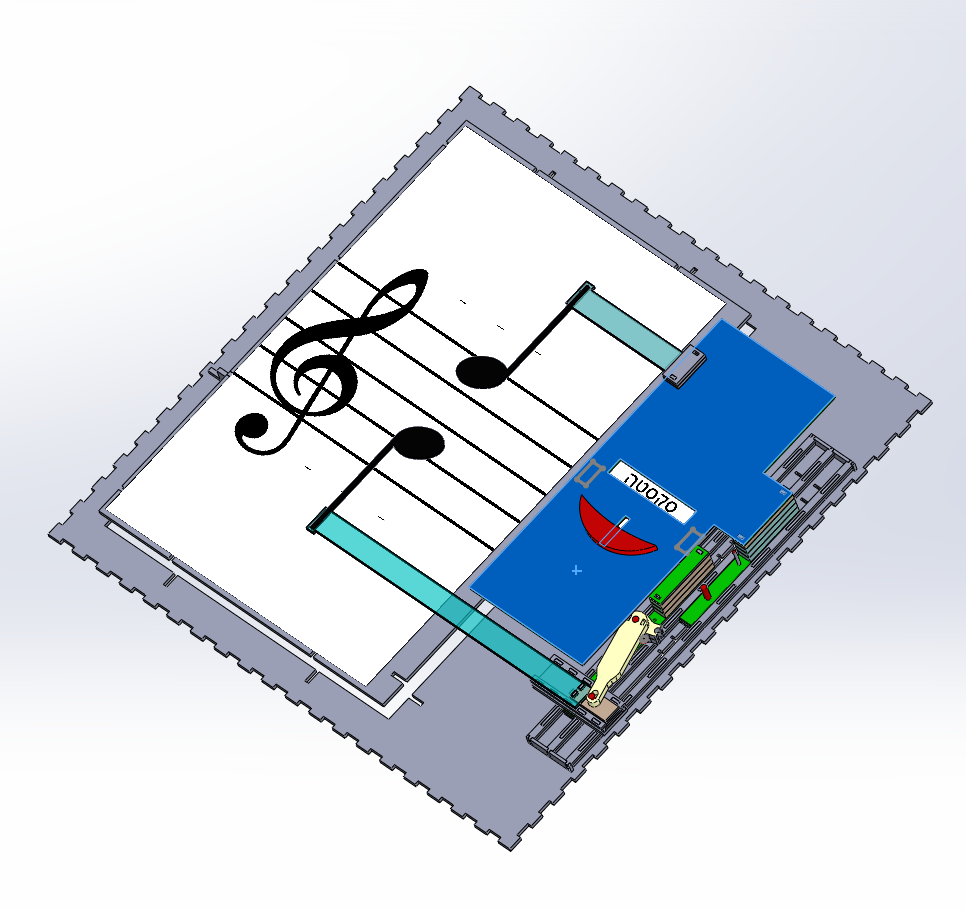
(BTW this is what the small parts are about: a mechanical device that shows the name of the musical interval between any of two given notes The writing is hebrew)
You are right, it is important to arrange the subjects in a way that saves time and material.
However, the result is not always as desired in this way. Sometimes the time saving does not justify the reduced security that the items do not fall out as expected or stand up and are a danger to the laser head. In the case of large projects on spikes, the plate itself can also collapse if there is not (enough) material left between the items.
Regarding the construction of parts, it took me some time to change the habits I used in 3D construction programs to pure 2D, like in LightBurn.
I construct pretty much everything I produce in LightBurn and I think I’m doing fine. With a little experience, the construction times are not bad.
I have done a revision of your project, is this how you intended? It looks like it’s a pretty clever device you’re making.
It’s perfect now, thanks. I believe that designing the parts directly in lightburn could allow skipping the solidworks stage, but the main reason why I decided to do solidworks first is that it allowed me to assemble all the parts together so that I could see if they would work eventually, and believe I had a ton of silly mistakes till I got to this point. And once the cuts will be made I suspect there’ll be more…I agree that eventually it would be useful to be able to design on lightburn, could come handy for example like with the problem of the glued line I had now. Glad u liked my project, I have a few more on the line, each dedicated to a different subject in music theory. BTW I am a classical guitarist, teaching at the Jerusalem Academy of Music
Hi Bernd, me again. Another question: some of the parts in my project need to slide smoothly within one another. I have read that the recommended gap between moving parts in 3D printing is 0.1 to 0.3 mm, but assuming that the laser cut can provide a more accurate result I wonder if I could get away with less, which I would prefer. At present I have planned the outer shaft to be cut on the line and the inner moving part at an offset of 0.05 mm. Too little? As you suggested before I have arranged the parts so that they don’t touch each other. Still tight, but there is a gap. Any further remarks? Thanks in advance. Yehuda. 2mm parts only lid etc.lbrn2 (146.2 KB) 2mm parts only.lbrn2 (57.2 KB)
The laser kerf will be about 0.2 mm wide, but it is not exactly any particular dimension, because it depends on:
the material being cut
inconsistencies throughout the material
the laser beam shape
If you are cutting plywood, the kerf width will vary based on the wood grain orientation and adhesive thickness in each layer. MDF or acrylic can produce more uniform results, but the exact width can only be determined by experiment on each lot of material.
Focusing my CO₂ laser on the top of an acrylic or MDF sheet produces a 0.2 mm kerf that gets narrower toward the bottom, even though the beam should be optically wider, because the vaporizing material attenuates the beam power. Depending on a variety of factors, the bottom kerf width may be close to zero.
So your design must accommodate a kerf that is neither constant nor uniform: the edges of any given path may actually cut ±0.2 mm from the nominal position, measured side-to-side and top-to-bottom.
I think @ednisley gives a good answer to your question… However, it must be taken into account that you have a diode laser which can give slightly different values. As a starting point, a diode beam is a bit smaller than the beam of a co2 laser. However, if you use more passes to cut your parts, the kerf will likely be slightly larger. My best advice would be to draw the items in their original size and fine tune the final size with the kerf settings. As @ednisley also notes, there is always a difference in how the parts fit together, depending on material properties. I make 2 puzzle parts for the different materials which I test the fit itself. I want to have most boxes and technical parts tight and for this I usually use kerv 0.075. (you enter the value into LightBurn and the program distributes the required values itself)
Your drawings look ok to me, you have the option of marking parts individually or in groups for the “cut selected graphics” function. Your shapes are closed, this is important, otherwise kerf setting will not work.
Kerftesttool.lbrn2 (39.0 KB)
With the small test pieces, you can easily change the kerf setting plus and minus until it suits the task, then you use those values on your layers. (You cannot use my power and speeds setting)
ps. If you zoom in a lot in the preview window, you can clearly see the plus or minus fit of the items (kerf)
Hi Ednisley and Bernd - thanks a lot, I really appreciate.
I failed to mention that I plan to cut the parts on a 2 mm thick acrylic using a laser diode machine (sculpfun9) which comes with an 0.06 cutting beam. In any case your answers maded me realize that after a few trials and errors I will probably be able to get the desired result. The example u sent me Bernd is very useful, especially since I am never sure if my settings don’t happen to be just the opposite of what I mean…
BTW my machine has arrived a few weeks ago, but I haven’t had the courage to assemble it so far, it’s still in the box… besides, since it comes without an enclosure I’ll need to build/get one before I start working with it. In any case I thought it would be wiser to send the first trial to a pro if only to steal a few tips.
Thanks again - Yehuda
I won’t be able to do that, as far as new machines or technical equipment are concerned, then I’m like a child, I’m impatiently waiting for the postman to finally arrive with my package.
Hope you get time during the Christmas season to assemble the machine and enjoy yourself.
Acrylic must be colored if you want to have a chance to cut it with a diode laser, I hope you were aware of that before you bought the machine.