Cutting circle 14 mm acrylic

Hi all,

I have an omtech 80w co2 laser and want to cut 14mm acrylic. When I cut a circle all the way through, the shape on top is circle but on the other side it’s an oval… I just can’t figure out why this is happening and how to fix this. Any help on this?

Thanks!

1 Like

Hello, good day

Are you talking the shape itself or the other side of the cut material?
Please share photos/screenshots to try to help you.

1 Like

Hi!

I’ve attached two photos. So the hole on the top is a circle and the back side the same hole is an oval. Even the piece that is cut out is also on one side nice and circle and on the other side it’s an oval…


1 Like

Have you measured each side with a caliper? I can’t tell from the picture if it’s an actual oval on the back or if the paper has just melted back a bit. Try it with a lower power setting maybe?

Thanks for your reply! I did peal off the backing and noticed that it’s not only the backing but also the actual piece. Also when you let it roll of a table you see from the rolling that it’s not a perfect circle.

I’ve already tried aligning the laser head to see whether it had something to do with that, but no. Also did I try multiple settings, low power, more power, but no luck. If only I knew where to look for the problem, I could try even more options. But unfortunately I don’t understand how this could be caused

The only other question I’d have is regarding focus, though I wouldn’t expect that to lead to oval, just a bit of a distorted circle from top to bottom. I could see a smaller circle on top than bottom but the oval is confusing. (ETA: I’d also be surprised if it was even noticeable in that size/thickness)

image

1 Like

I’m using a 3inch FL lens and align the height of the focal spot to be in the middle of the material, so 7mm. I’ve also tried my 4inch lens, but get the same results. If the top would also be an oval, than it wouldn’t feel that strange. But the strange part is that the top part is indeed a circle only the bottom part is turning into an oval

That’s just really odd. Maybe get in touch with Omtech support? They’ve been pretty responsive to me.

I mean it’s the heat from the process that deforms your parts. Normally the acrylic evaporates, but from about 10 to 12 mm into the material there is a tendency for the walls of the cut to melt together and make it harder for acrylic vapors to escape. I have done some work with 15 and 16mm acrylic a year ago and observed similar deformations, especially on smaller items.
If I remember correctly, I got my best results with 2 passes and the speed as fast as possible, max power and only air to keep the nozzle/lens clear. (60 Watt machine, standard 2" lens, minus 5 to 8 mm focus to the surface)


2 Likes

:+1: on @bernd.dk comment on air assist… use the least amount of air pressure with acrylic…

I do 6mm (1/4") quite frequently using the least amount of air pressure. Never attempted 14mm… I have a 40W machine…

:smile_cat:

Thanks! Glad to here I’m not the only one who has/had this problem. I will try some more with more speed and see is this does the trick.

In my opinion, Material Tests are the basis for being able to master one’s machine and the various materials. If, on top of that, you find the optimization process interesting and have the necessary time for it, then it is “quality time”. It’s a little geeky but I love it.
It will be interesting to hear from your tests if you find any settings for the small items in +14mm acrylic, after all you have an extra 20 Watt to work with. :wink:

I indeed like to process of figuring out how to get the best results. I did some tests with your advise as well and found out that 1-pass seams to be the answer. 2ms, 85% power, little air and 1-pass gives me the best results.

There is still something I need to check with omtech. In the manual I read 20ma is max but also recommendation to use the machine between 10 and 95% power. But the ma reader gives me 20ma at around 40% power. So does this mean I need to keep an eye on the reader not to exceed 20ma or can I use it up to 95% power in lightburn?

As a starting point - no. If you want to use the LightBurn power scale, you must adjust your high voltage power supply. I haven’t done it, but @jkwilborn will probably come up with a good explanation and help you with advice on adjusting the power supply if you want to do it.

My OMT 60Watt machine, which is probably close to a 50-55Watt CO2 tube, I run with a maximum (rarely) 18mA and as standard no more than 16mA. This is what was recommended from OMT this time for my machine. I know these are pretty conservative limits, but so far I’m fine with it. Despite fairly intensive use of the laser for almost 2 years, only a minimal reduction in the power effect can be observed.

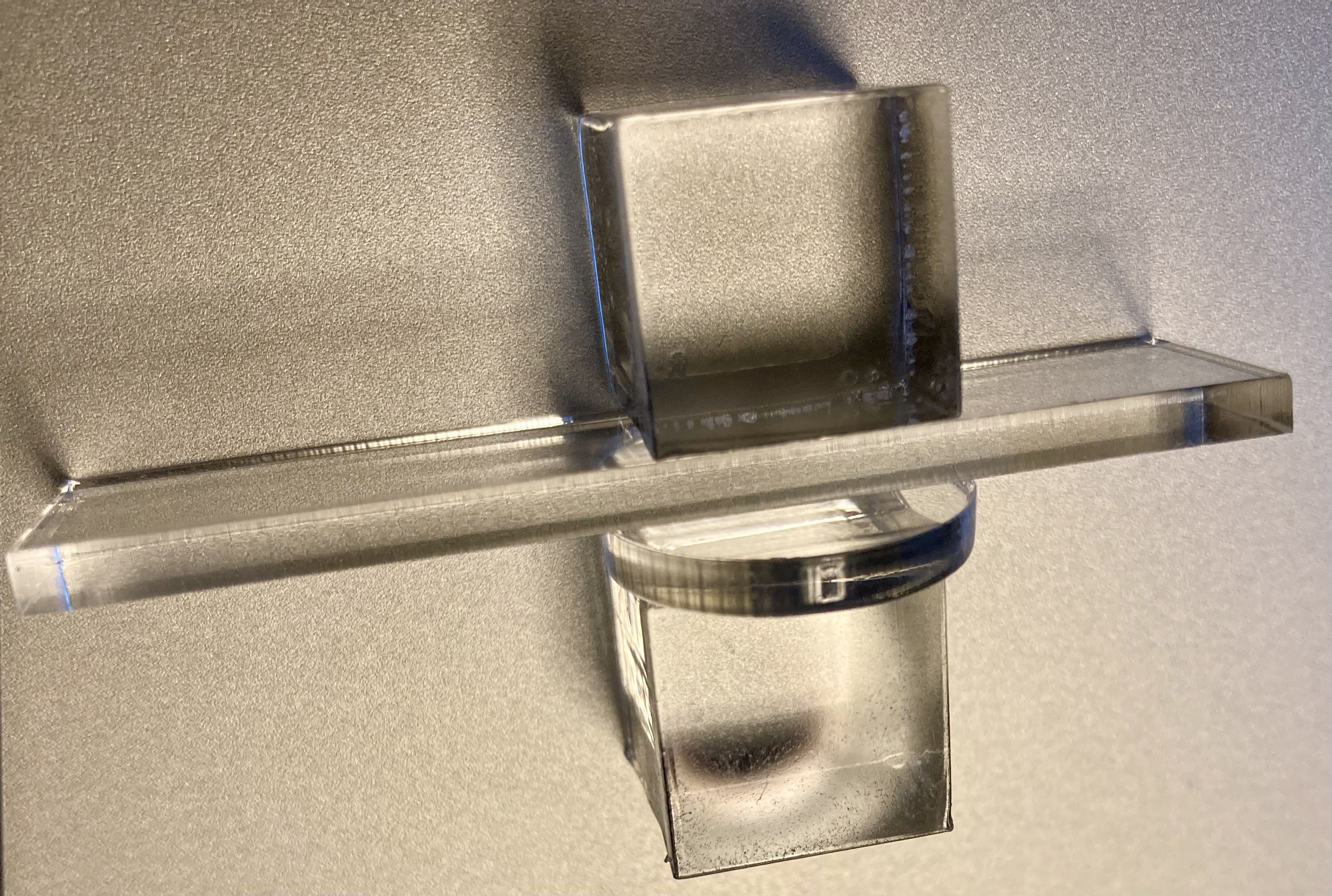
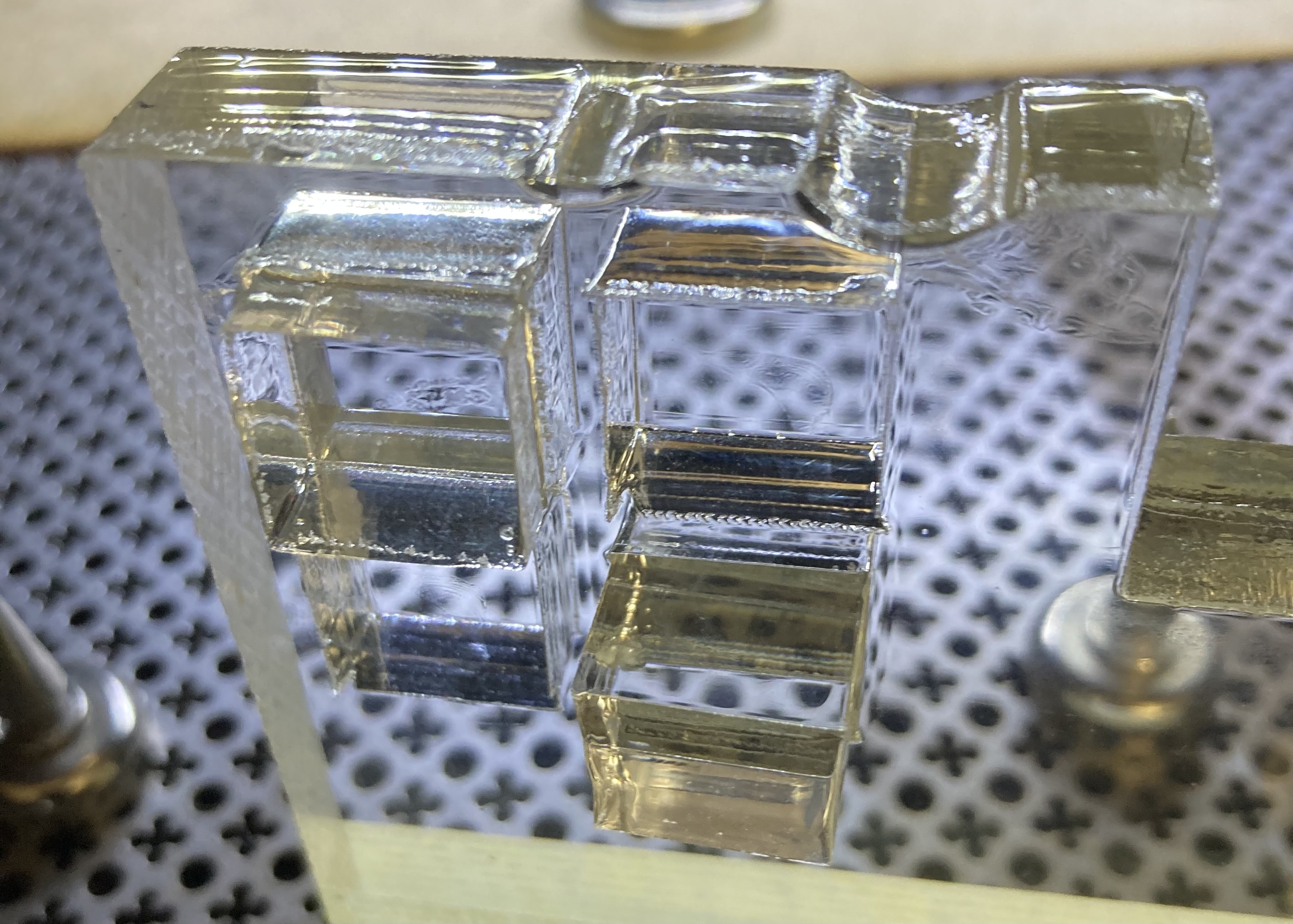
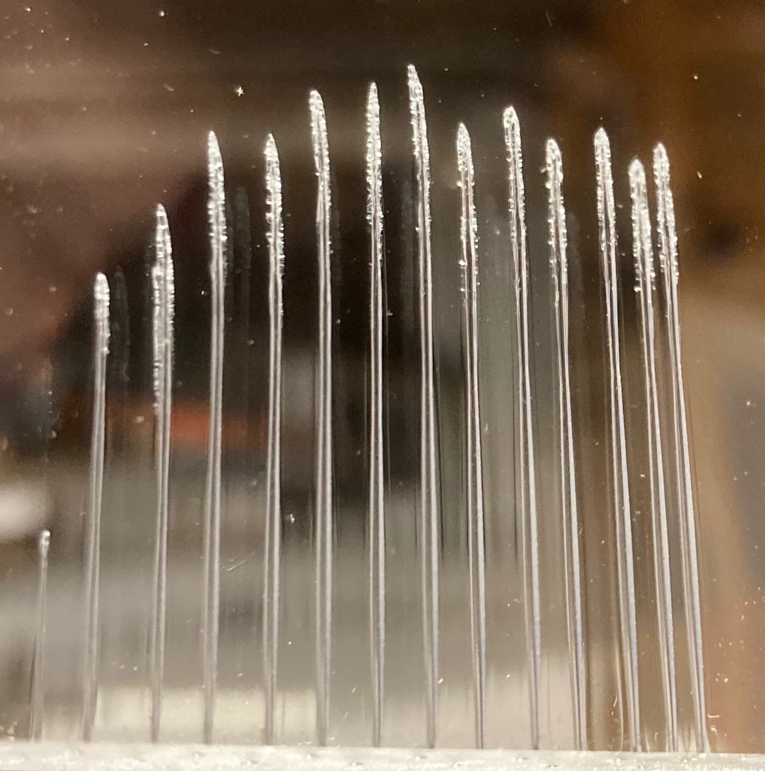
I can recommend doing a test where you find your tube’s maximum effect, you will be surprised. The test is that you use a thick piece of acrylic (15mm on a high edge, for example) and shoot with approx. 2-3 seconds a series where you increase power with e.g. 10% in LightBurn. I achieved my deepest penetration at 70% in LB, which corresponded exactly to 18mA. Then the result will actually be less deep again!

The values are, from left to right (in LB%), 5, 10,20, 30,40,50,60,70,80,75,85,90,95,100

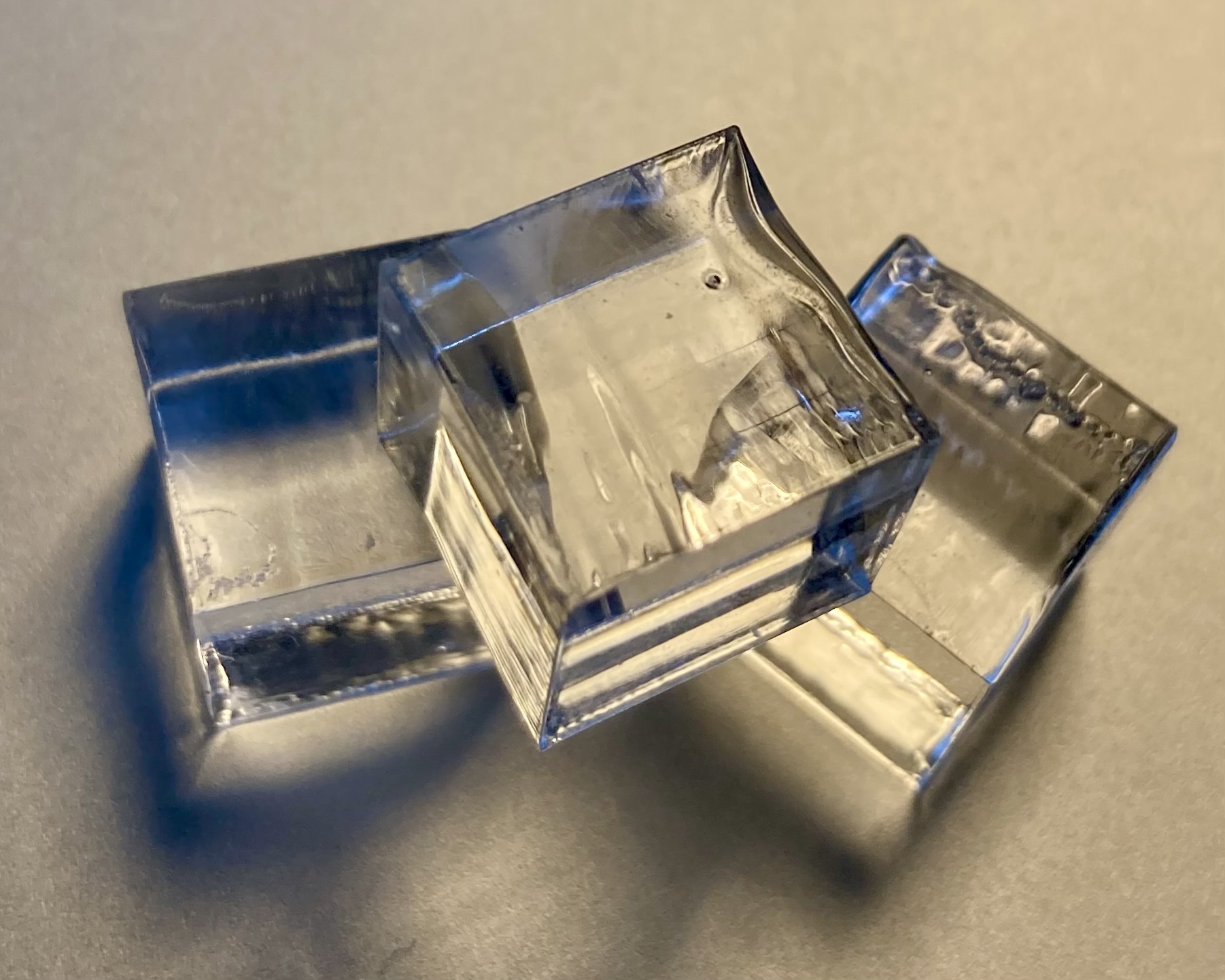
To cut 15-16mm acrylic I used 18mA - 70%in LB and 2.5mm/s, 2X
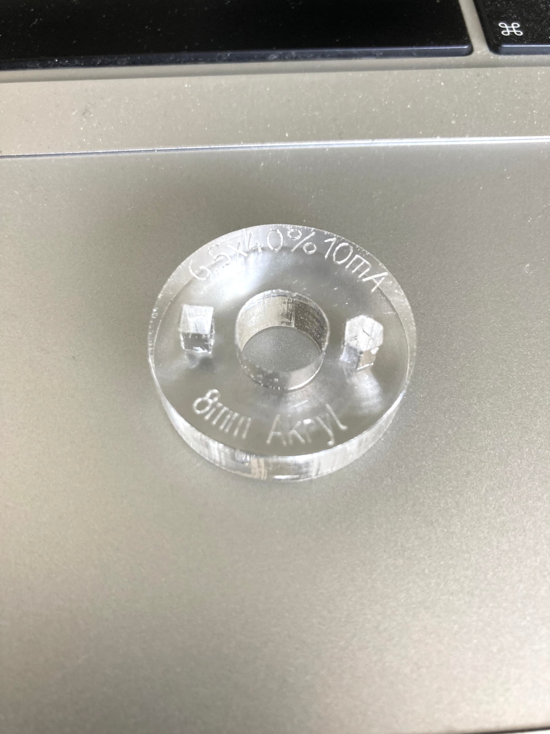
For 8mm acrylic my values are, 6.5mm/s at 10mA - 40% in LB, 1X

note, the square is 3x3mm

3 Likes

There were a few good answers here, especially the ones about melt as the laser burns down. However, there could be one more possibility, mechanical alignment of the focus tube. If it is not perfectly perpendicular to the material, the top of the material would be cut perfectly, but as you go down the material, it will be a cone. The thicker the material, the more pronounced it will be. If you cut the same pattern in wood of the same thickness, and you still see the oval vs circle effect, than I think it is mechanical. If I had more time, or a better sketcher, it would be easy to show how this could be the case. ( I had this issue once. ) But I hope you can envision this. So, possible solution as well.

1 Like

Thanks everyone for the reply’s! I also got a reaction back from OMT to try not to exceed 70% power in LB. But I will also do that test to see what % is 20mA

Any laser control software should generate a 70% pwm (or power) to the lps. It’s irrespective of the software…


In my view, analog meters seem to be the best here, as I know how they work…

A digital has to sample the current… you don’t know what or when that sample period is…


First you have to know what current you want as 100%, normally this is the maximum working current… This is for a reci… I’d use recommended current for one of these…

I’ve also used this as a guide… seems to be a bit conservative… My original tube was 880mm in length and the documentation stated 21mA…


These few steps to setup your lps current limit.

I will use the 20mA for what I want as 100% power (pwm).

Set the console to 50% power and the pulse to continuous… Hold the pulse until you can get a good reading of the current.

Adjust the lps internal pot to read 10mA… this will allow 10mA when you set the software to 50% power…

Done… :wink:


This is where I have to adjust mine, a real pain to get to…


Good luck

:smile_cat:

2 Likes

So let me check if I understand what you’re saying.

Let’s say my max output is 25mA based on the chart. When I want 100% in LB to be this 25mA I have to set 50% on my console, fire and read what my digital mA meter is showing and adjust it at the bottom until it shows 12/13mA? This way I know that when I set 100% in LB this will be this 25mA?

This means I have to adjust my material library I’ve created for the different materials?

Yes, it is unfortunately necessary to revise your material library. The same also applies to all your saved projects.
But the actual adjustment of the pot from the lps is the biggest problem, as @jkwilborn writes, it is a physical challenge to find and turn this small screw into the lps, through a small hole. You see nothing, what you hit in the hole is pure guesswork. More professional electricians will probably screw the lps itself from the back wall to be on the safe side during the operation. (and laugh at my worries)

As I have mentioned, I have not adjusted my lps, I know all my relevant values and it feels normal to me that 16mA is 65% in LightBurn and therefore my 100% - max.
Problems only occur when I import lbn2 files from sources other than my own for tests or problem solving and I overlook or forget the power settings of a layer which is e.g. set to 100%. Tried it twice, but nothing violent happened because it only lasted a few seconds. But there is a certain risk of accidents.

1 Like

Is there any downside in adjusting the lps to that the % is corresponding to LB?

And what kind of screw driver is required for the job?