Hi ![]()
I’m using LightBurn for a while now. There’s a problem I keep having where angled\curved sections of my designs are not cut through. Cuts would work perfectly in the x/y directions, but when the movement involves x&y motion at the same time, cutting does not work as well.
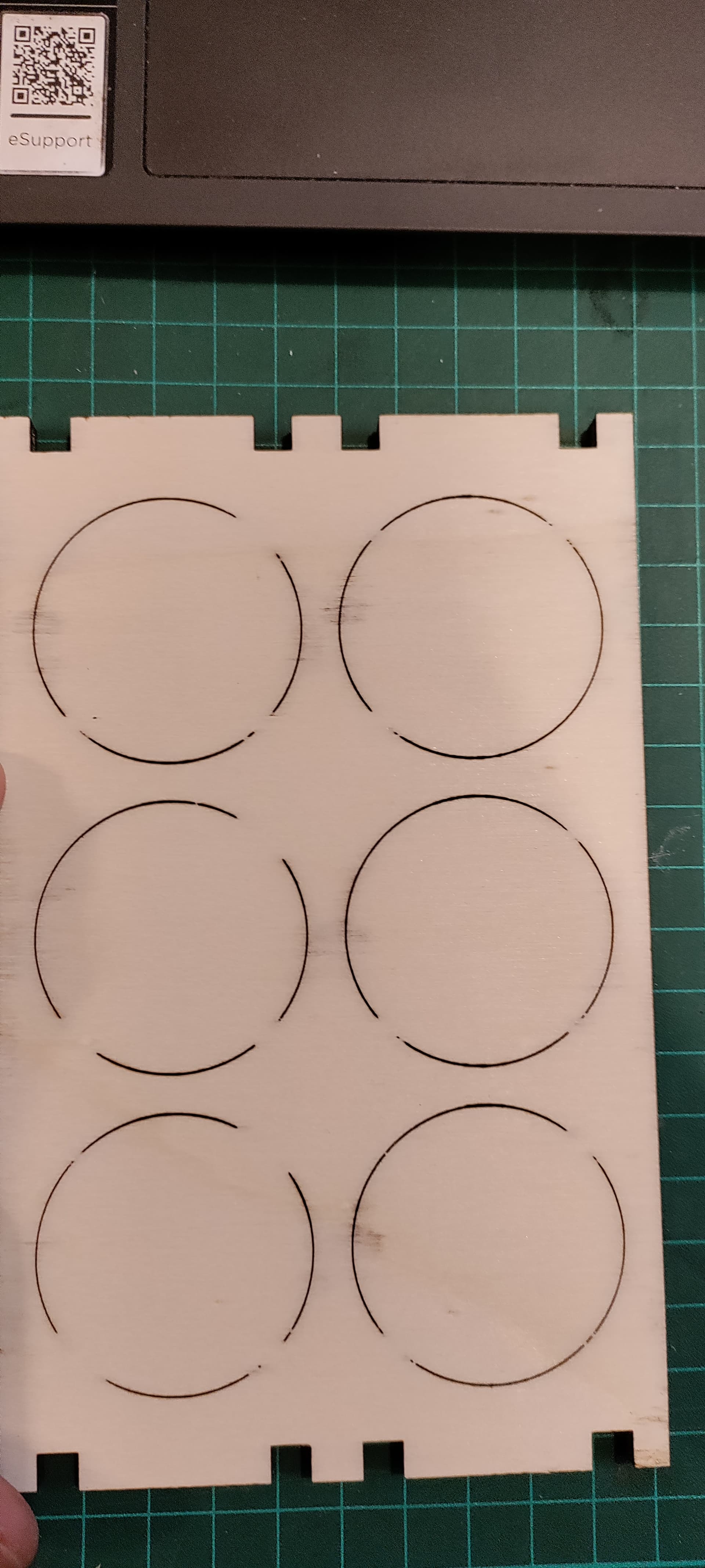
See the attached images - paths at about 45 degrees were not cut all the way through.
Any ideas? Looks like the software is over-compensating for something but I have no idea what. All I know is that the problem is not the material itself.
Thanks in advance!
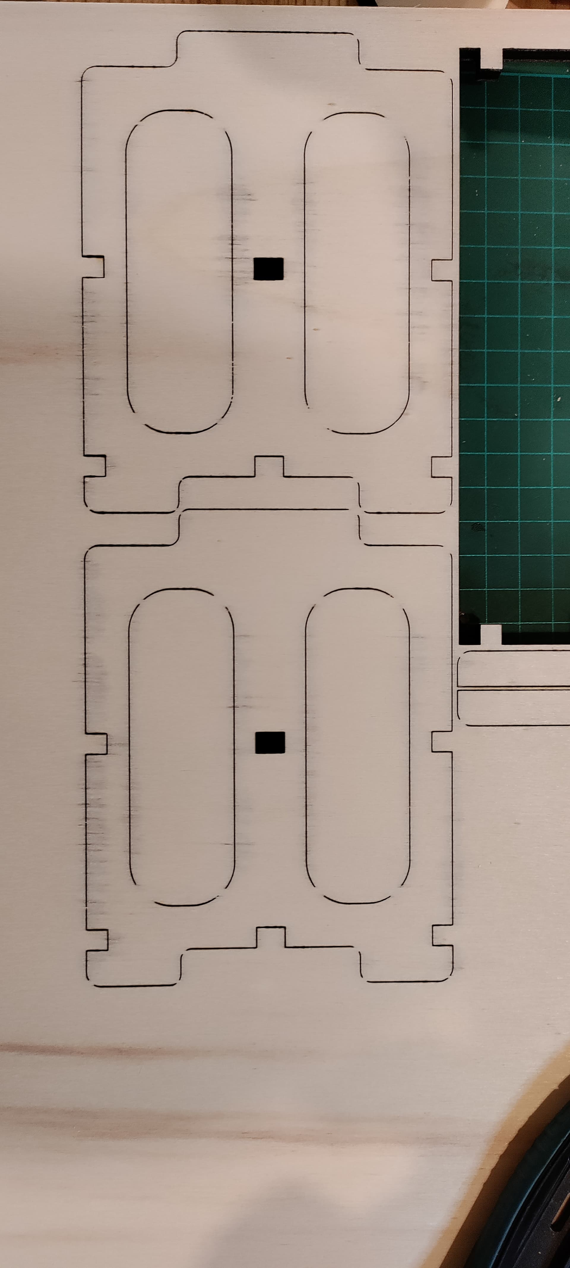

Thanks for the reply ![]() Yup, it’s turned off, and as you can see, the “tabs” have different sizes and positions (and it doesn’t happen with straight paths)
Yup, it’s turned off, and as you can see, the “tabs” have different sizes and positions (and it doesn’t happen with straight paths)
unfortunately, but it was a qualified attempt ![]()
Stupid question, are you showing the front or the back?
can you upload the file here?
That’s the bottom side - the laser does cut these sections, but not as efficiently, so when viewed from the top things would look fine.
Sure, here’s the file ![]()
Coffee Jar Holder (5.7mm).lbrn2 (28.8 KB)
In general GRBL implementations will reduce power when decelerating/accelerating as what occurs in the change of direction in a corner.
The amount of reduction is directly affected by the perceived scale of speed reduction.
I suspect 2 potential things happening here:
- Your machine is reducing speed (and thus power) considerably due to your speed settings. You could try reducing your initial speed to see if this goes away.
- This could be a firmware bug and the implementation from xTool is simply over-reducing power during deceleration. xTool implementations have many similar firmware bugs so wouldn’t surprise me if this were the case.
There are no errors in your file as I see it and I think @berainlb hits the spot with what he writes, just like so often before.
Thanks a lot for your reply ![]() Both of your answers talk about acceleration, which would explain rectangular shapes with rounded corners, but a circular path should have a rather constant acceleration, shouldn’t it? So I would expect that circular parts would not be cut at all, no? However, the sections that are not cut have the same orientation as the others.
Both of your answers talk about acceleration, which would explain rectangular shapes with rounded corners, but a circular path should have a rather constant acceleration, shouldn’t it? So I would expect that circular parts would not be cut at all, no? However, the sections that are not cut have the same orientation as the others.
Thanks a lot for the help and tips, I’ll try to contact xTool support too, I wonder if that’ll work.
This may just be a function of how the motion planner is setup, an overly simplistic variable power adjustment, or a bug. In any case, it’s almost certainly something related to power or motion.
if we are talking about a closed circle yes, but still with 2 start/stop changes of acceleration.
What does a circle look like with your machine?
There are circles in the images I attached, some problem ![]()
I guess the start/spot will be around the same point too, and I have 2-4 of these semi-cuts… weird.
I’ll try to cut some things at different angles and see what happens
So in your opinion, would this be a problem on the machine side or lightburn?
Thanks again!
100% on the machine side. LightBurn only specifies power and speed and generates the path of the shapes. The controller does the rest in this case.
Too bad I guess, if it were in LightBurn I guess there would be a solution, eventually. This is not guaranteed with xTool ![]()
Thanks for the help!
Try reducing cut speed. That may result in less perceived deceleration.
I’m already at 6.5mm/s ![]() I could over-kill the rest of my cuts, but I’ll try contacting xTool first
I could over-kill the rest of my cuts, but I’ll try contacting xTool first
Hi.
Since the non-cut through sections are roughly at 45 degrees as You pointed out, two things come to mind.
First:
While You are somehow sure that it’s not the material, if -and usually it always is- the plywoods and construction cardboards (Your material looks like one or the other) are cross-laminated or fiber cross-oriented, there’ could be streaks of something in the material that requires more power than the rest of the material.
Especially if it’s not “laser approved” material.
Secondly:
If the laser head wobbles even a tiny bit, the beam hits the sides (or even the material surface unevenly) of a curved cut and the penetration suffers.
If You have acess to automotive feeler gauges (or a microscope), measuring from the cut side will reveal whether the cut is uniform in width or not.
It should be roughly 0.1mm, depending on the material thickness and number of passes.
If the cut is wider at the places where the cut has not gone through, examine carefully the play on all the bearing surfaces.
Mine (D1 Pro 20W), for some reason developed really bad play on the X-axis within the first few hours of operation.
Also:
Because of the way it’s formed, the xTool beam shape is rather unforgiving.
While the 20W 455nm on mine is much better than the 2W IR, if You haven’t done so in the past, do a ramp test to determine the exact focus distance of the head.
The less power the head has, the more important is the correct focus, obviously.
While the xTool “focus arm” provides a reasonable compromise, it may or may not provide the correct focus.
On the 2W IR I have it’s definitely not, the arm is ~1.5mm too long.
With that kind of power -or more exactly a severe lack of it- one definitely does want to squeeze every last drop of performance out of it by ensuring the focus is spot on.
Also, make sure that if Your D1 head has the focus fine tuning ability, it’s set at 0 if You want the focus to be on the surface, and something else if You want the focus to be below the surface.
Regards,
Sam
This topic was automatically closed 30 days after the last reply. New replies are no longer allowed.