To be honest, I have no idea of what you are talking about. The only way I have is to set a speed (let’s say 300mm/s), I run it on a specific job (per instance 2 parallel lines of 1000mm each) and compare the actual completion time. As on now, I see no time difference to complete a job above 300mm/s.
the overall performance improvement gained by optimizing a single part of a system is limited by the fraction of time that the improved part is actually used
In your case, the total job time includes travel time from & to the parking position, the (short?) non-cutting moves between the vectors, the speed ramp times on both ends of all the vectors, and a whole bunch of other stuff I can’t recall right now. With that much overhead, reducing the actual vector cutting time for only the long vectors, even by a factor of two, will have little effect on the total job time.
What was the job time for your test pattern before you did all this tweaking and what is it now?
It’d still be interesting to measure the actual vector speeds, even if they really don’t make that much difference. I gotta gimmick up a pattern for that and release the oscilloscope …
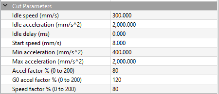
I’m aware of all that and I think we are going way too deep for a simple problem, what machine parameter limit my cutting speed at 300mm/s even if I input a speed above that, but allow a speed of 1000mm/s for idle, for engrave (FILL) and for move?
I’m thinking acceleration is likely the problem. In a previous part of this thread there’s a hint about it taking time to get up to speed.
Let’s say you need to cut a 1000 mm long vector. If you’re acceleration is 1000mm/sec/sec, that doesn’t mean you’ll get to the end of the line/vector in 1 sec. It doesn’t mean though by the time you reach the end the head would/should be travelling at that rate.
Now, if you have to stop and start along the way every few mm as you descibe, you’ll never see the head reach its maximum speed even if the acceleration rate has been set to 1million KMH.
In the machine setting, there’s no distinction between the X axis and the Y axis in the cut parameter.
I was assuming that if I cut a straight line over the X axis only, the speed limit of the X axis will be involved, but in reality, the software still check what is the lower speed limit between the X and the Y and in my case, even if the speed limit of the X axis was at 1000mm/s, the Y axis was still at 300mm/s therefore, for every cutting job, this last one was the limit.
Once the Y axis was increased to 1000mm/s, I can now cut at this speed.
Thanks for your replies guys, I appreciated your help!
I don’t normally add anything to this forum but I have to ask. According to you machine specs that show maximum cutting speed at 30,000mm/minute. Isn’t that 30,000 divided by 60 seconds equal 500 mm/second?
Exact, I tried this speed in the past, while it’s good for cutting straight line or continuous curves, rapid direction change like cutting letters are not that good.
Sounds like we’re getting into Zen Koan territory here.
I’d expect to apply the axis limits after calculating the individual speeds based on the vector’s speed and angle. Maybe there’s a goof in the calculation due to special-casing 0° (and probably 90°) vectors around the trigonometry calculations.
Maybe, but probably not. My understanding is the hardware implements the fill operation if it’s in multiples of 90 deg. Otherwise the software has to generate the code.
It’s probably done with smoke and mirrors anyway… one of the reasons for not losing the smoke…