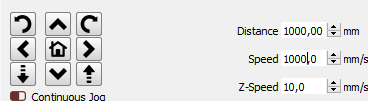
Hi, for a special project, I have to cut at 1000mm/sec but my machine refuse to go above what seems to be 500mm/sec. I went to the machine, modified the Idle Speed to 1000, the X axis max speed is at 1000mm/sec because I’m able to move at that speed but even if I input a cut speed of 1000, it runs lower that that.
It’s not a matter of acceleration because I’m doing my test over a length of 1000mm and as I said, I able to MOVE at 1000mm/sec so what is limiting my cutting speed?
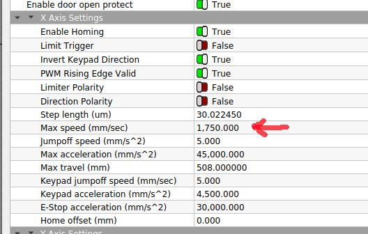
Both the X and Y axes settings have a Max speed value that sets the upper limit for motions parallel to the axes. The upper limit for diagonal cuts is sqrt(2) higher, which is what vendors quote as a machine’s “maximum speed”.
For your 1 m test line, it’ll hit full throttle and run just fine.
However, when cutting anything other than long straight lines, the speed will rarely reach the maximum value, because the acceleration limits the maximum speed for short vectors.
You can visualize that by engraving a 10 mm square and using Preview (*) to measure the overscan distance. For my X axis with an engrave acceleration of 4625 mm/s², the head takes 16 mm to reach 400 mm/s from a standing start. In the Y direction, with an acceleration of 1850 mm/s², it’s 43 mm.
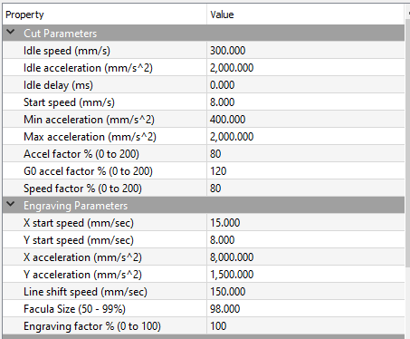
The simulation settings show a much lower Cut Acceleration of 1500 mm/s², which seems set by the Idle Acceleration value. How all the various number / factors / axes interact is a mystery.
At 1500 mm/s², any vectors shorter than maybe 50 mm, including curves, will run at a lower speed. The path planner surely optimizes the transition between non-collinear vectors to maintain the maximum possible speed, but the details of that aren’t well documented.
Bottom line: IMO you can set 1000 mm/s, but achieving it on practical patterns will prove challenging. Verifying the actual speed would be an interesting project!
It would be a Good Idea™ to back up your machine settings before making too many changes …
(*) Use Edit → Device Settings → Additional Settings → Read from controller to fetch the current values for the Preview.
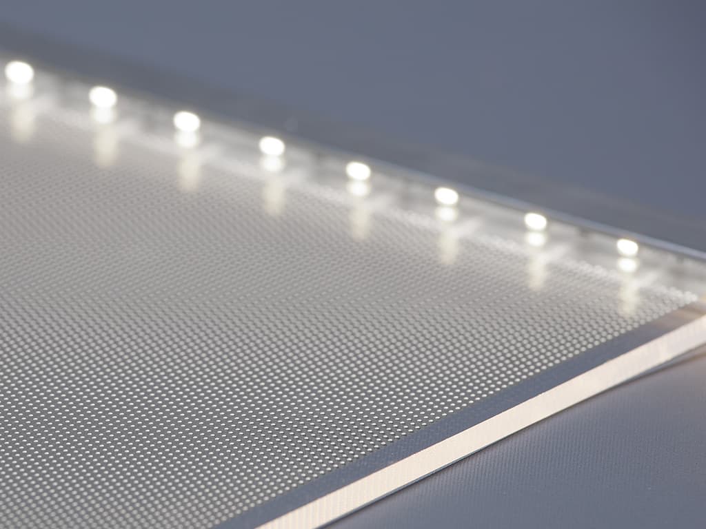
First of all, what I want to achieve is to engrave dots to create a light guided plate once lighted from its edge. What I currently testing that works great is to use a lense offset to increase the spot size and use the DOT mode. This method gives good result but is too slow at 500mm/s therefore I want to increase at 1000mm/s.
I know I’m moving at 1000mm/s because it takes about 1 second to move 1000mm
I see a huge speed difference when moving from 500mm/s to 1000mm/s but whatever I input a cutting speed of 500mm/s or 1000mm/s on a 1000mm straight line on the X-axis, I’m cutting at the exact same speed.
I tried on Lightburn and RDWorks and got the same result therefore it’s not a software issue.
I may not be understanding, so please advise if I need adjustment.
When using Dot Mode, the laser will start and stop along the path or pause and pulse. This impacts getting up to or reaching “full speed”. My assumption, is if you change that to a single cut line (turn Dot Mode Off), your results would be more in line with what you’d expect.
Dot Mode
When enabled, the laser will pause and pulse at regular intervals along the path, instead of cutting continuously. The ‘Time’ value specifies the pause delay in milliseconds, and the spacing parameter sets how far apart the pulses are. This can be an effective way to do stitching holes, or cut very thin or delicate materials, but the constant pausing can shake the machine - using Perforation Mode is often preferable for this reason. This setting is not available on all lasers.
Unfortunately, already tried, a straight line cut at 500mm/s or 1000mm/s run at the same speed. Even weirder, at 1000mm/s, it cuts slower (maybe at 500mm/s) but come to the home position fast (at 1000mm/s).
And my bad, I confused mode, I’m using perforation mode since the beginning, not the dote mode.
I assume you jest, as you have been doing the LightBurn for a while. But, to offer clarity, ‘Cut’ and ‘Line’ can be used interchangeably. With the release of 0.9.00 we changed some naming in the LightBurn UI.
[Oz] Changed Cut/Scan to Line/Fill - easier to understand for beginners
I didn’t make this hardware, and don’t know exactly what it does under the hood, however 1000mm/sec with a 0.1mm ‘Perforation’s’ would imply the hardware being able to process 10000 instructions per second, through whatever planning buffer is in there, and that is unlikely.
Even if it can go that fast, it needs to NOT go so fast that it can’t stop in time if the next move to come in is a full stop. I don’t know how big a lookeahead it has, but when not in “raster” mode, it’s going to be considerably slower.
Actually, I use the perforation with 0.5mm ON, 2mm OFF therefore a lot less data than what you think. If we can figure out my problem, I’ll be able to test it at least instead of speculate.
The best way for them to get what they wants might be to create a bitmap and run in threshold or pass-through mode, because that would be doing a Fill, scanning horizontally using the hardware scanning path instead of the cutting path. Cutting / vector marking isn’t really intended to go that fast, so there could be any number of issues, but raster scanning might be able to keep up.
I am additionally wondering what your system’s manufacture recommends the max cutting speeds for this machine configuration.
And add to those number, I upgraded the head for a lighter one, meaning less inertia.
You give me a doubt this morning about the FILL feature, I tried it and I’m indeed able to run at 1000mm/s so what is blocking me to cut (LINE) at this speed?
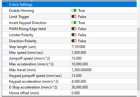
It would be helpful to see the values in the Machine Settings list. Most likely, one of the mysterious Factor settings limits the maximum cutting speed, although its name may not give much of a hint.
Post screen shots of the entire list so we can poke around inside.
In a rational world, Idle would mean Not Cutting, but AFAICT the fact that it’s in the Cut Parameters section suggests it has something to do with vector cutting.
I think the maximum vector speed is set by:
240 mm/s = 300 mm/s × 0.80
Change those to 1000 and 1.00, then see if anything falls off going around corners …