I wanted to calibrate the x/y axis.
I created a rectangle of 120mm in the y axis and 100mm in the x axis. The element was 100.68mm in x and 122mm in axis.
I made some corrections and now my laser burns a perfect rectangle of 120mm y and 100mm x.
Unfortunately, I don’t understand why, if I want to cut a 10mm x 10mm element, the result is e.g. 9.60mm x 9.80mm.
Why is the element negative if it is small and there is also a 0.20 mm difference in the axes.
I understand that I can calibrate each element separately, but I would like to set the laser once and properly. What tolerance do your lasers have?
Have you accounted for the width of the cut in your adjustments?
Assuming you have a 50 W laser (because of the name and Ruida controller), the kerf in plywood (and most materials) will be about 0.2 mm wide. If you calibrated the step distance using cuts through the material, the actual distance will be about 0.2 mm larger than the cut-out material. That means a 100 mm cut-out actually required 100.2 mm of motion and the calibration will be incorrect.
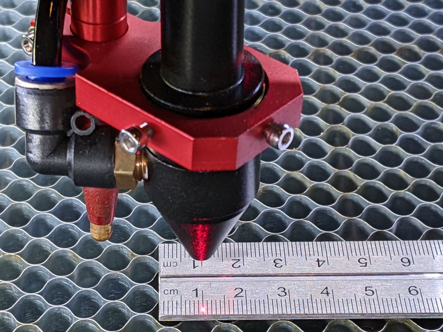
Recalibrate using either well-focused lines engraved on the surface or, if the machine has a red-dot pointer, manual moves without activating the CO₂ laser:
Wow, I must admit I hadn’t thought of that. By calibrating with the developed measure, I was able to calibrate the laser to 700mm, and not in small pieces of 100. Now I will be able to play with the kerf offset. But in the end I know that my laser is moving by equal lengths. Thank you very much, you solved the problem 100%.
It’s not clear what you mean: because the design has a notch and the finished piece has a notch, why is the notch a problem?
Now, if the notch is not the correct size, that points toward a mechanical backlash problem. Fixing that will likely affect your new calibration, but burn that bridge when you get there.
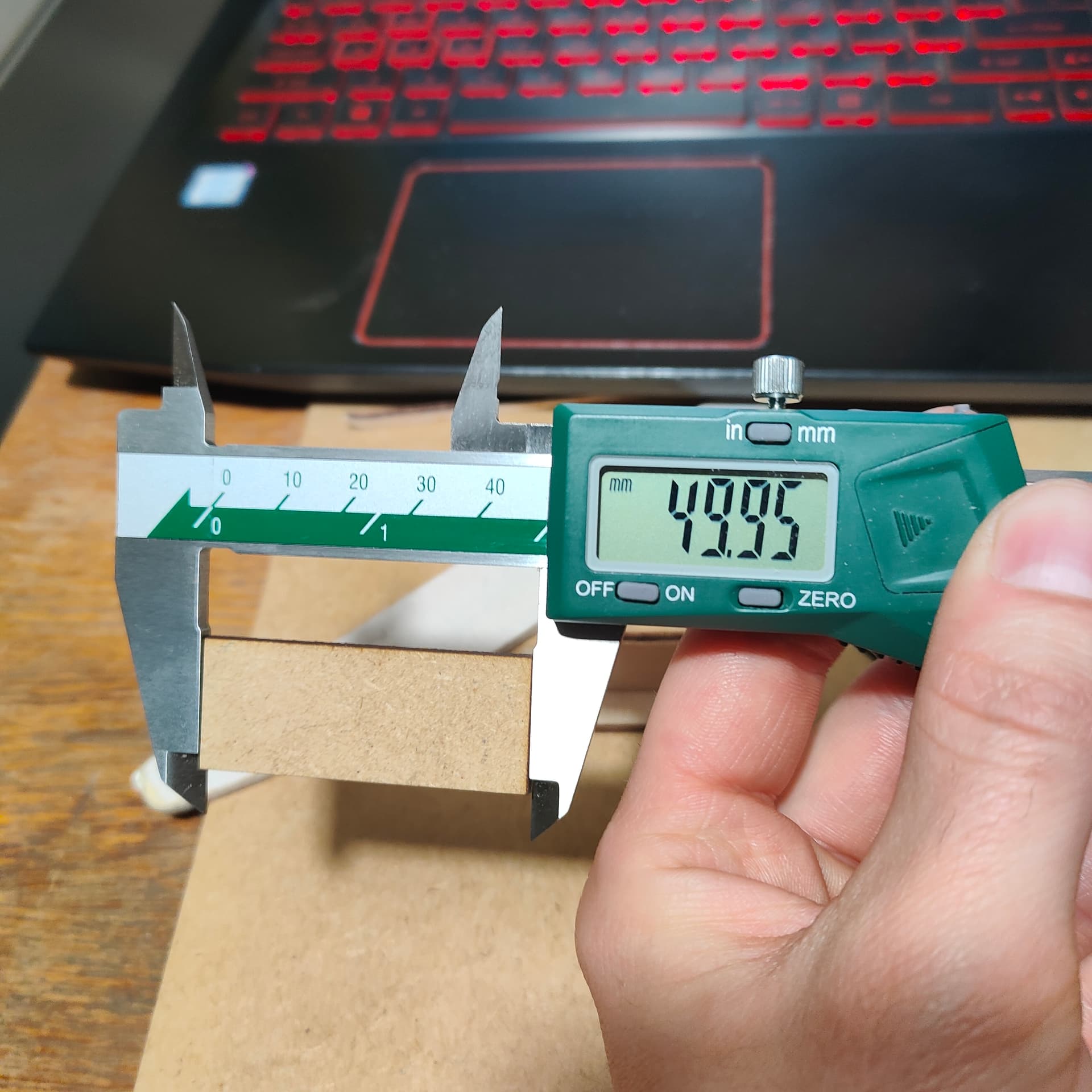
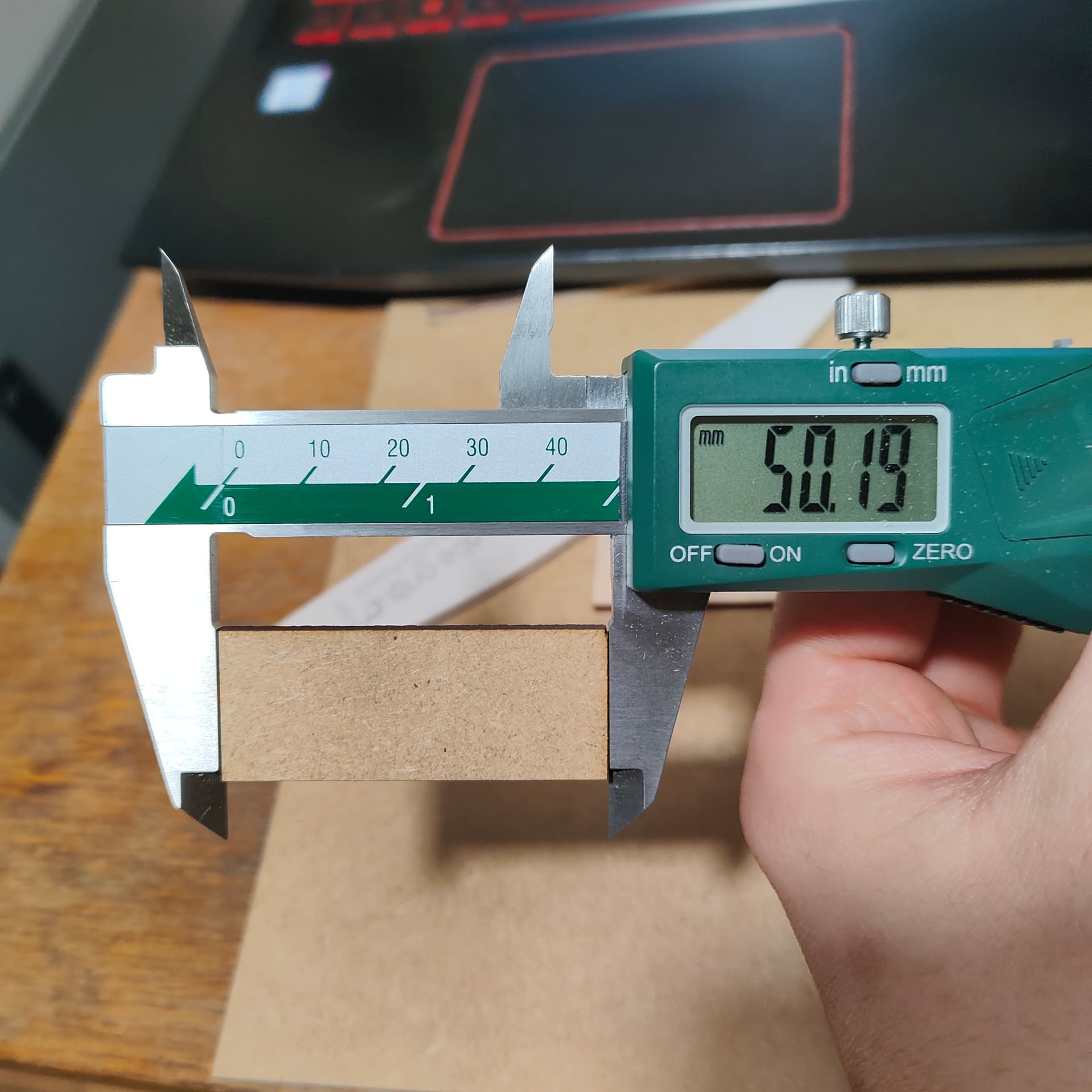
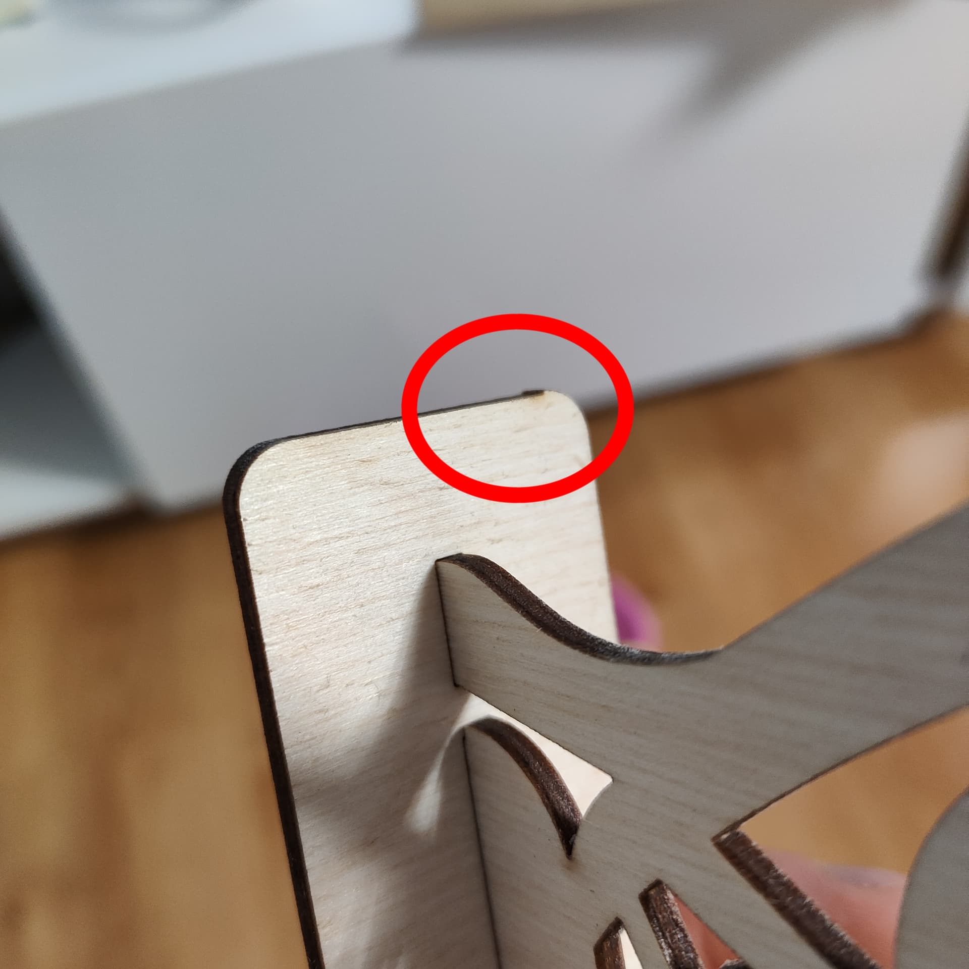
I’ll explain again. I drew 3 identical 50x20mm elements (rectangles). 2 of them turned out perfectly. In the third one there is 0.20mm in plus, on the x axis. And a strange tooth in the upper right corner.
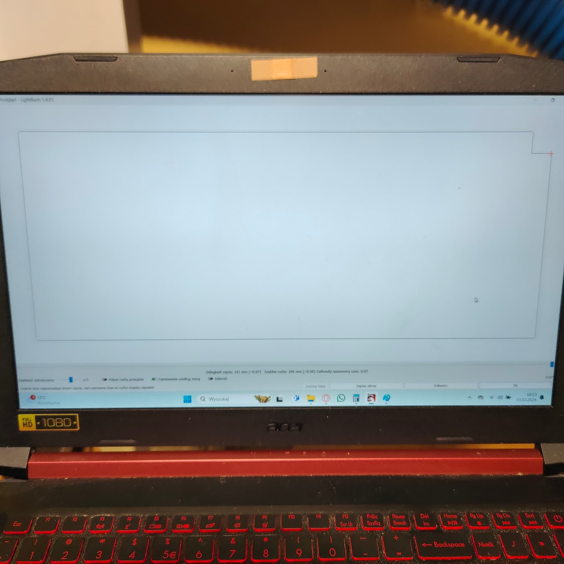
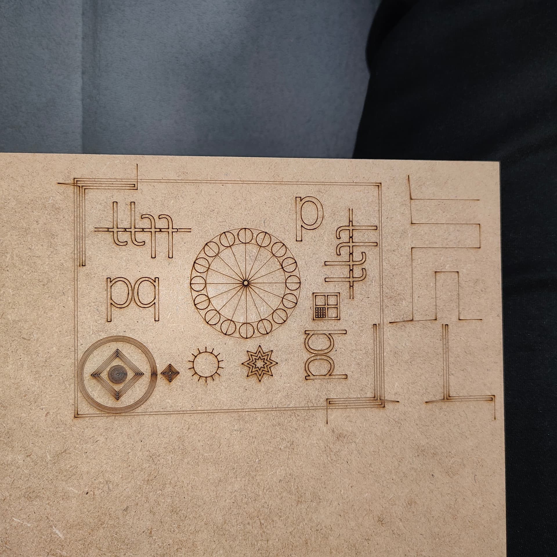
I assumed the photo of the LightBurn Preview matched the piece with the notch missing. If that’s not the case, what does it show and which piece did it produce?
If there is a difference between the LightBurn design and the piece from the laser, then suspicion falls on the mechanics.
Run that backlash test and let’s see if it reveals anything interesting.
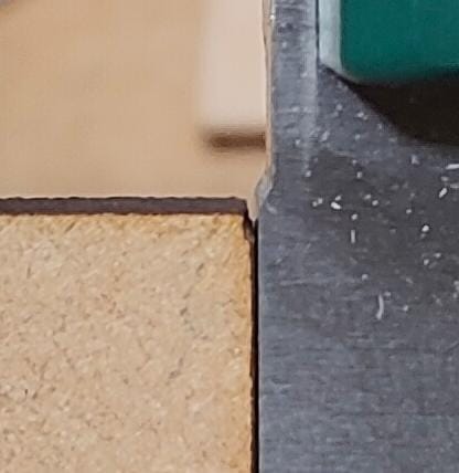
It looks pretty much as good as it’s going to get.
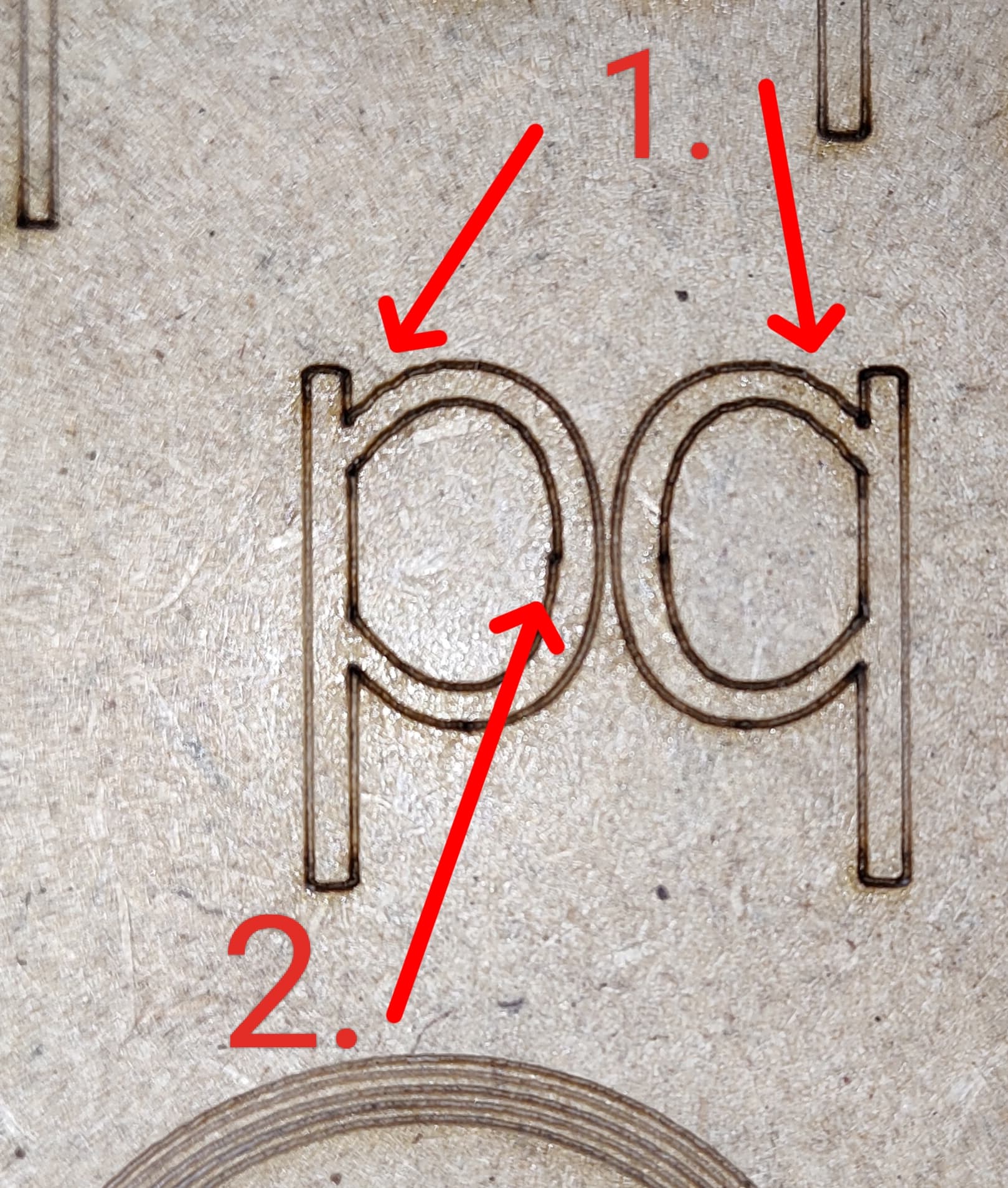
The head on a relatively large CO₂ laser tends to wobble slightly after rapid direction changes, as in the two curved areas you marked as “1”. It could be worse, as in that discussion, and reducing the speed (and power!) is the only way to reduce the vibration.
Similarly, the slight mismatch you marked as “2” suggests a very small amount of X axis backlash. Scrub through the Preview for that section and you’ll see the head approaches from the right to start the top half and returns from the left as it completes the bottom half. The mismatch is less than the spot size, so it’s on the order of 0.1 mm and basically at the mechanical limit.
What is not apparent is whatever is going on with the notch you mentioned; if it’s not in the pattern, then I have no explanation.
I thought maybe I was exaggerating a bit, there are some deviations, but tomorrow I will tighten/loosen the straps. Maybe I will achieve even better results. Sometimes there is a slight “tooth” when cutting out shapes. (photo) I will definitely want to neutralize it practically to zero. Tomorrow I will start using the HIDE BACKLASH function in the optimization options. (I have just found it, and it practically does not change the burning time of the elements). Thanks for your help, your way of calibrating axis steps is the BEST
AFAICT, that works by pushing the backlash to somewhere you won’t notice it in this design, but it will reappear in the most conspicuous spot in the next design. The only way to eliminate backlash is to find it and fix the mechanical cause.
Although the belt tension may be contributing, it’s most likely a slightly loose setscrew in the couplings or pulleys between the motor shaft and the laser head. They should be firmly tightened on the middle of the shaft flat to prevent it from rotating inside the coupling; the best way to verify that is to loosen the screw just slightly, then tighten it while rotating the shaft back and forth to ensure it settles correctly.
Some folks report stripped threads in those places, as well as in the laser head mount itself. Given that the backlash test came out well, IMO you should concentrate on finding and verifying all those little fasteners.
It’s tedious, but rewarding when the whole thing works the way it should.
The y-axis is literally perfect, the tolerance I can achieve is 0.10mm, so it’s really great. Unfortunately, the situation is worse with the X axis - it varies by 0.40mm. Is it possible that the belts may be stretched too tight?
The short belt on the engine is very tight (originally by the manufacturer).
Adjusting the long strap doesn’t change anything. It’s just tense.
I don’t know what I could really adjust on the X axis, but since the Y axis can be calibrated perfectly, I want a similar effect on the X axis
Basically, you are now in the realm where anything is possible, so you must methodically examine everything to find out what’s going on. There may be one problem, two problems, many problems.
What’s absolutely certain: nobody else can tell you what you will find.