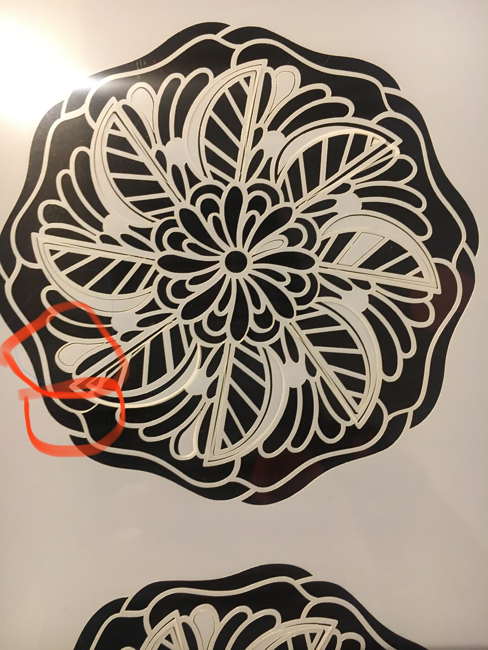
I’ve been struggling to figure out why my laser keeps cutting the design wrong on specific parts. I’ve tried cutting the design on different areas of the laserbed so it isn’t a problem with the machine and I’ve checked the file on Illustrator and Lightburn and there’s nothing to indicate anything different about these parts that keep being cut differently.
One of the parts that always seems to be wrong is cut quite early during the job so that eliminates the idea that the material may be moving each time (I even watched it cut to make sure!). Also I realised it was making the error even when I hadn’t figured out the right settings for the Mylar and was not even fully cutting through.
Does anyone have any ideas?
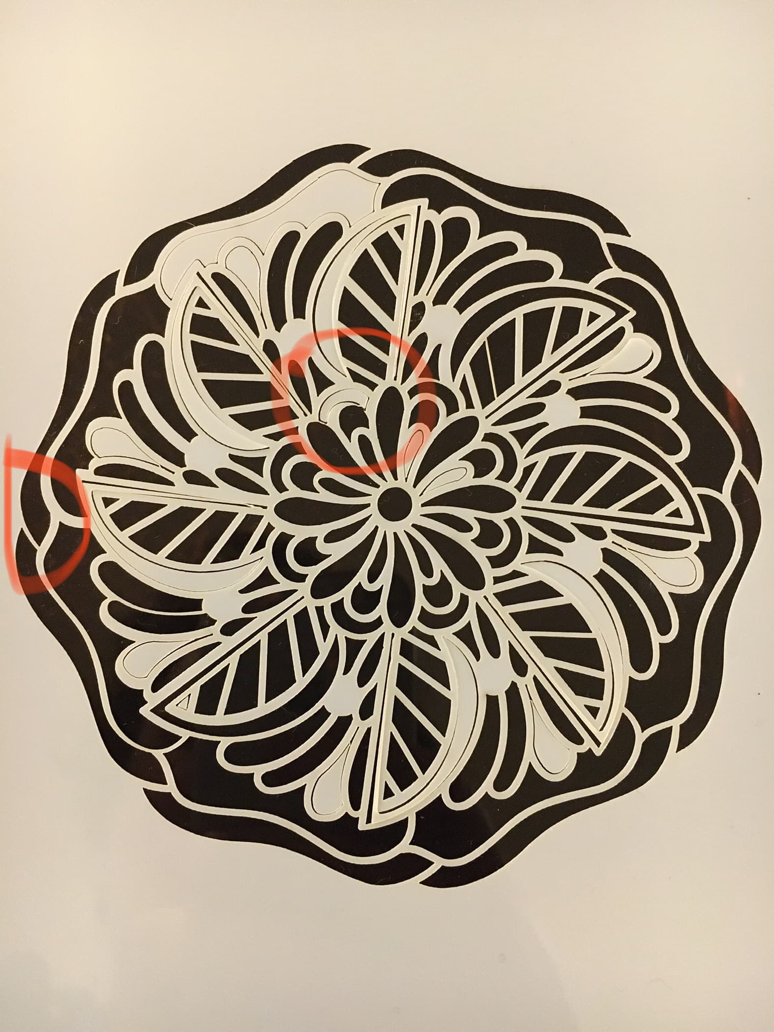
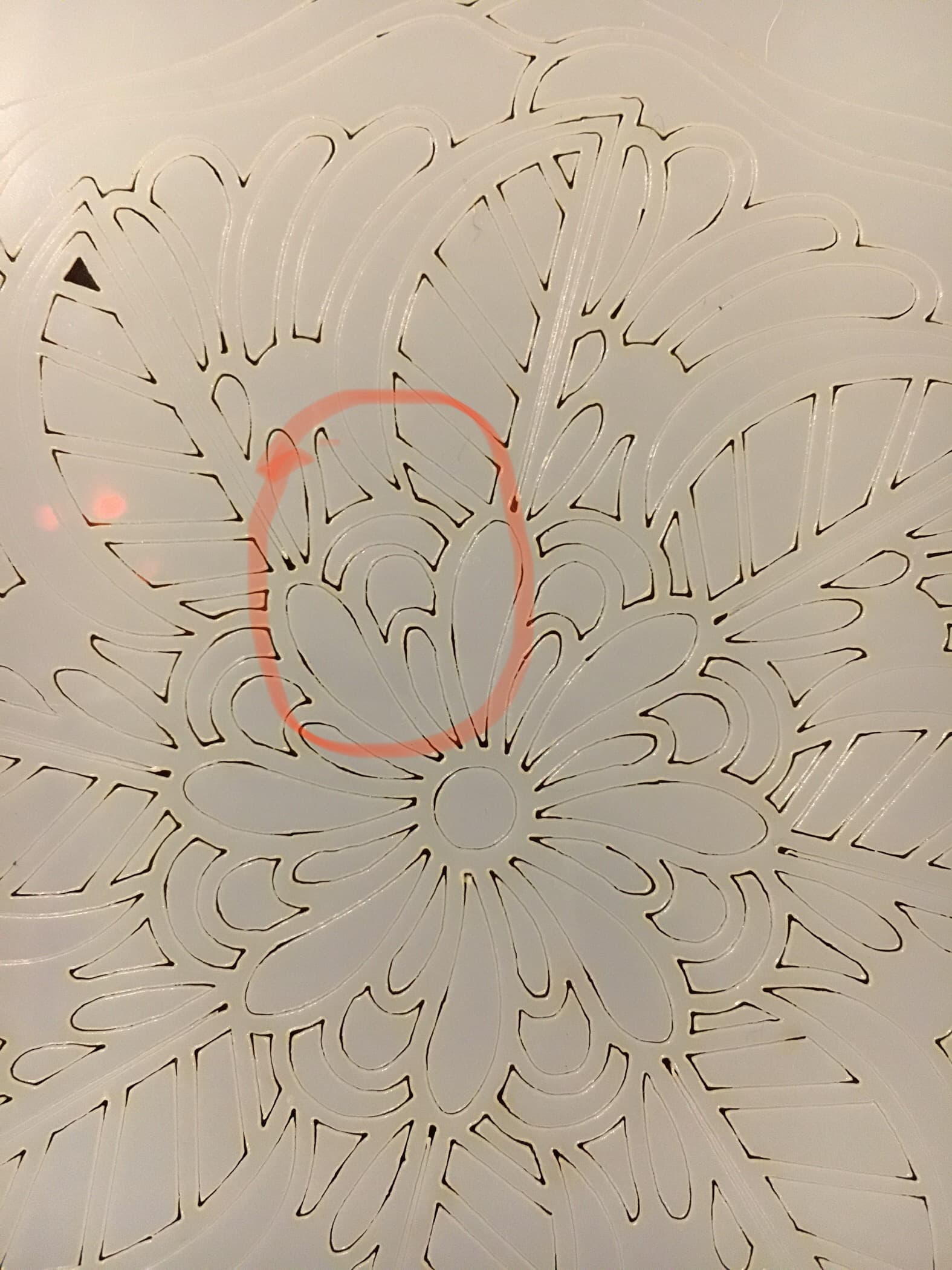
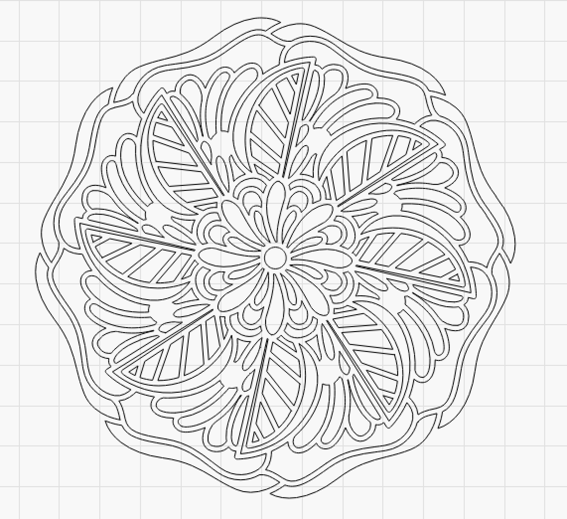
Here’s so pictures of it happening circled in red and the picture of what the design file looks like :
If you run the process in the preview window, do you get any errors?
I can test the file to see if there is a difference between the machines if you want.
I have the same setup as you except that my machine is 60 Watt.
Problems like that almost always come down to a loose part somewhere in the path from motor to laser beam.
Because it’s reasonably consistent in the examples you show, I’d start by scrubbing through the preview to find the motion immediately before the misplaced shape. The direction of that motion will provide a clue to what’s loose.
If the X and Y axis motors have pressed-on pulleys, they’re unlikely to become loose. However, the setscrews in the couplings between shafts, particularly in the Y axis, can loosen just enough to allow the coupling to jam between two positions. Checking that will require you to reach inside the cabinet with your head and hands in unlikely positions.
A large CO₂ laser may also have a loose mirror on the gantry, a focus lens rattling around inside the tube, or a slightly loose laser head, so check all of those places to find something that moves by less than a millimeter.
I could not see/find an error in the program or preview.
I’m a bit skeptical if it’s the mechanical part of the machine, the visible errors are so singular and “perfect”, it’s as if information has been lost from the drawing to the machine, but it’s more of an unqualified get.
If it’s any consolation, everybody says that before they actually find the problem, because we all know software is such a crapshoot.
Which looks exactly like a setscrew shifting from one position on the shaft flat to another: the error rocks back and forth between two stable values. If the pattern of motion never applies enough force to shift the screw, the machine works perfectly. When it shifts, you’ll see a single offset and then everything works perfectly until it shifts back again. Rinse & repeat.
Running exactly the same pattern with exactly the same speeds, which is what we all do when something goes wrong, pretty much duplicates the previous results, because the setscrew sees exactly the same forces at exactly the same times. We then conclude it must be software, because the hardware is obviously fine.
This kind of backlash is devilishly hard to find, because the setscrew feels tight. You must loosen it enough to let you rock the shaft back and forth while slowly tightening the screw, so that it ends up centered in the flat and firmly snugged down.
IMO, “LightBurn the program” gets a good deal of blame for problems due to “the LightBurn configuration for my laser”, none of which have anything to do with the program code itself.
Loosen a couple of screws and you’re in the minefield of desktop diode lasers.
First off sorry for my lack of replying closer to the time, I have finally been able to set aside some time to carry on with my laser and it’s “problem”, I’d hate for my lack of reply to come off as rude after you all were so helpful, so again sorry and thanks.
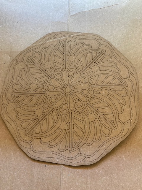
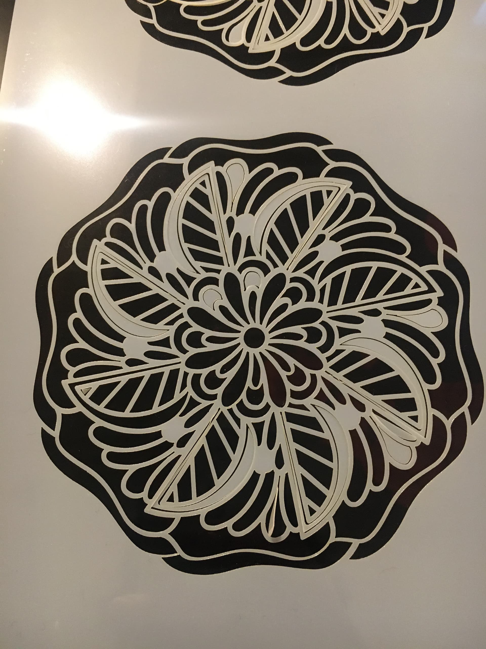
Secondly, it’s pretty ingenious of you Ed to have figured it out going of such a small details. I have since got deep inside my machine and tightened every screw I could get to and the results are the pictures above. The first cut resulted in no more of the errors presenting themselves in the same places as the other cuts but still had a few new errors in new places. However I was able to rotate the design slightly and it seems to now avoid the problem motion enough to get a better cut.
I realise now whilst typing that I may have become confused at what you meant my ‘shaft’ and in fact just tightened the rails whereas you may have meant the moving piece with all the laser head, air assist etc on? the “loosen” and “rock the shaft back and forth while slowly tightening the screw” is what is throwing me.
Thanks again for all your help, I wouldn’t be anywhere close to an answer without the expertise here.
Backlash is where you find it. Loose linear slides seem unusual, but would definitely cause positioning errors. If those screws were loose, then you have a very strong hint the folks assembling the machine were not paying attention to their jobs.
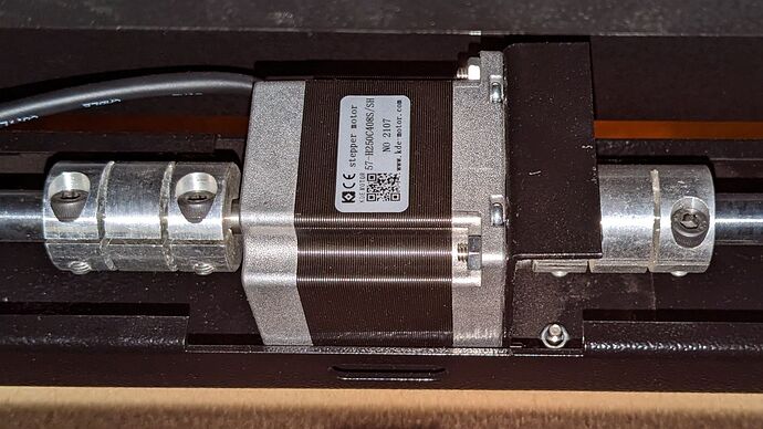
However, I was describing the setscrews securing the couplers / pulleys / whatnot on all the rotating shafts between the motor and the laser head. For example, here’s the Y axis motor hidden in the back of my 60 W OMTech laser:
The motor drives a pair of jackshafts turning the Y axis belts on the sides of the machine. Any one of those four setscrews can be loose, so that the motor shaft or the jackshafts can turn slightly inside the coupler.
There are other setscrews in other mechanical joints, any of which can be at least part of the problem.
Again, the setscrews can feel tight, because the shaft has rotated and jammed against the screw. You must loosen the screw, then rotate the shaft or coupler while tightening it, so that the screw ends up tight against the middle of the flattened section of the shaft.
Simply tightening the screw on a slightly rotated shaft will give you a false sense of security, because the shaft will rotate the other way, away from the tight screw, and there’s your backlash.
It’s painstaking work in awkward positions, but there is no substitute.