Did you ever have a circulation switch installed? If so, it’s already connected at that end. I had my 5202 up real quick.
The diagram is in the ‘fault’ mode or powered off as written. I used the wires from the factory flow switch.
One wire goes to the controller, one to ground. When the connection between H1 & H3 is made, pulling the controller line down the chiller is indicating an ‘ok’ condition. The reason is if the device power fails (like unplugged) the relay will open and the Ruida control line will go high, indicating a fault.
Same operation for the limit switches. They just pull the inputs to ground indicating they are ‘active’. If you watch your controller you’ll see the LmtY- and LmtX- LEDs toggle when the limit switches become active.
The controller box can trigger a few errors under certain temperature conditions, but it signals OK if the water is circulating, even if it’s over the ‘turn on’ range. Mine turns on with a green light when the water temperature it 34 deg C. There is an upper ambient air and water temperature limit on that controller that will cause a fault. I think the KM is the Kompressor Module. The t-switch just turns it off and on.
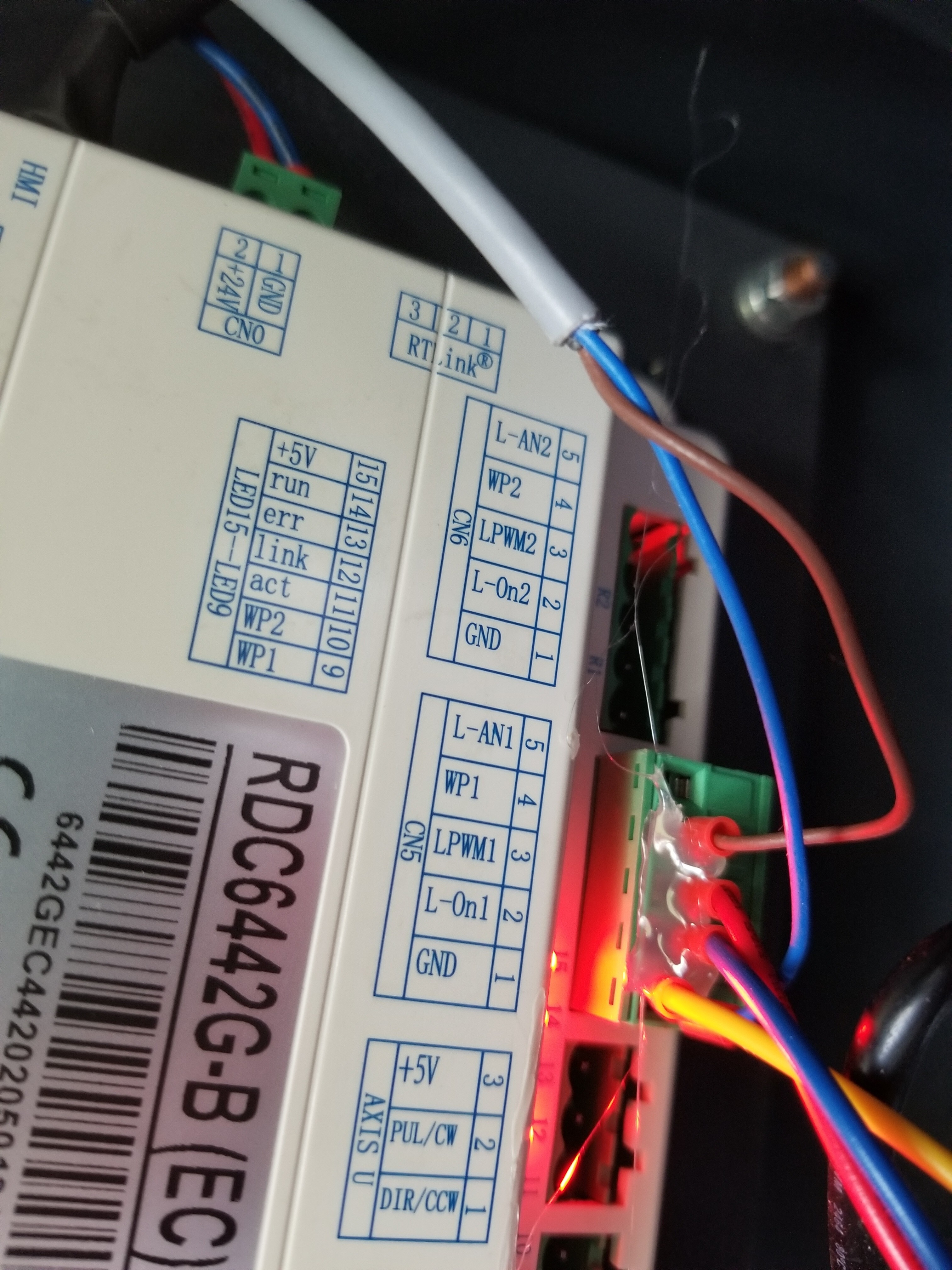
Here’s the wiring to the Ruida. Notice the gray twin conductor with the blue and brown lines. These connect to the H1 & H3 connections.
Also notice there is NO 24v here. It is ground (blue) and controller input (brown into WP1). It’s a ‘wired or’ input, like all of the Ruida 'input’s, so when it’s pulled low the device is ‘ok’ or active.
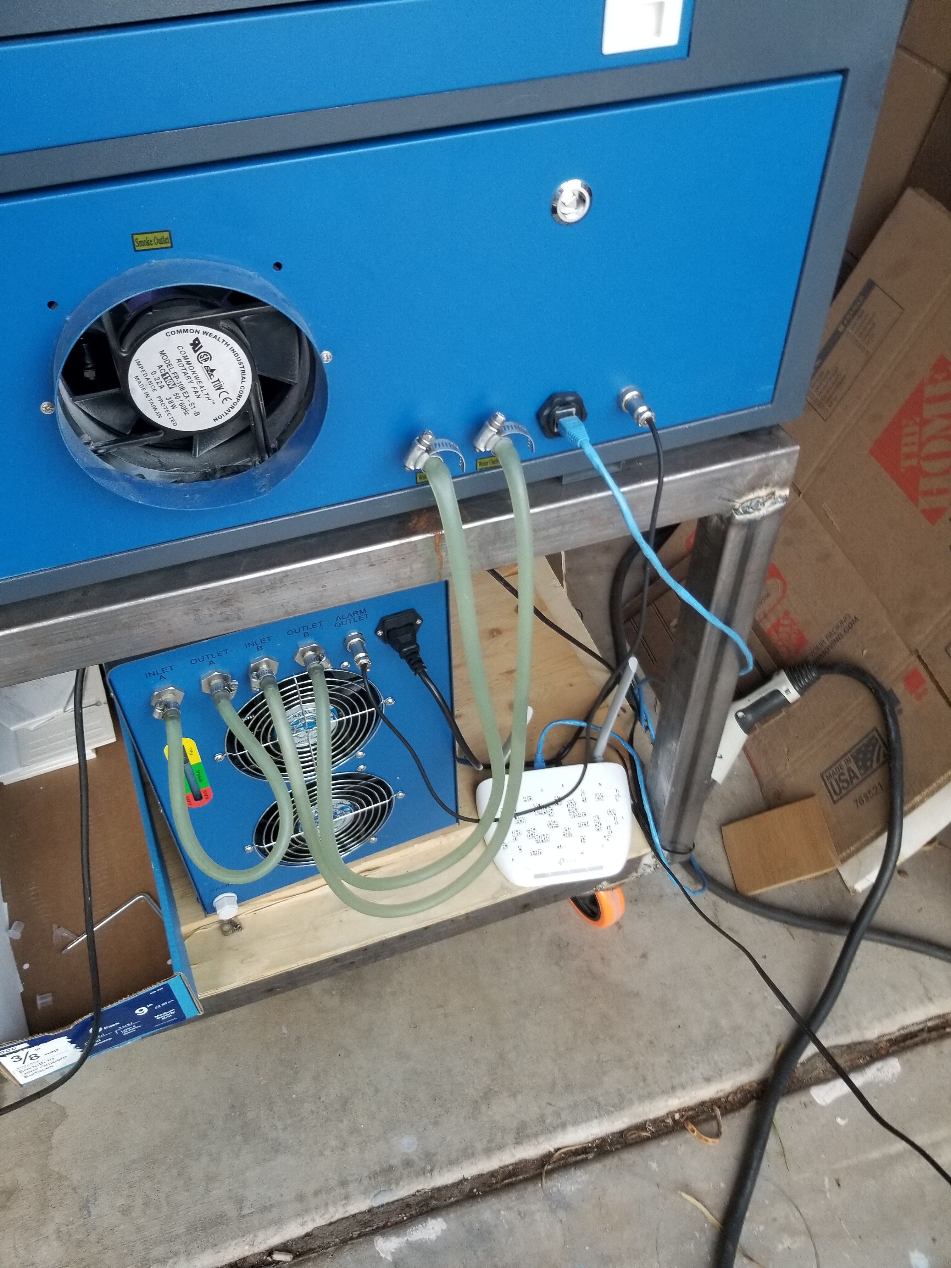
Here’s where the ‘gray’ line goes out to the chiller connector.

Good luck… Take care…