Hello,
I have problems with the cylinder correction tool.
i do these steps en looks like the correction tools is way off
I show the steps in the image.
is there something i doing wrong perhaps ?
Hello,
I have problems with the cylinder correction tool.
i do these steps en looks like the correction tools is way off
I show the steps in the image.
is there something i doing wrong perhaps ?
Can you explain what you’re trying to do? It seems you’re trying to use this for rotary. And are you intending to do this on your Atomstack X20?
Cylinder Correction would only be relevant for galvo systems and applies to non-rotary situations.
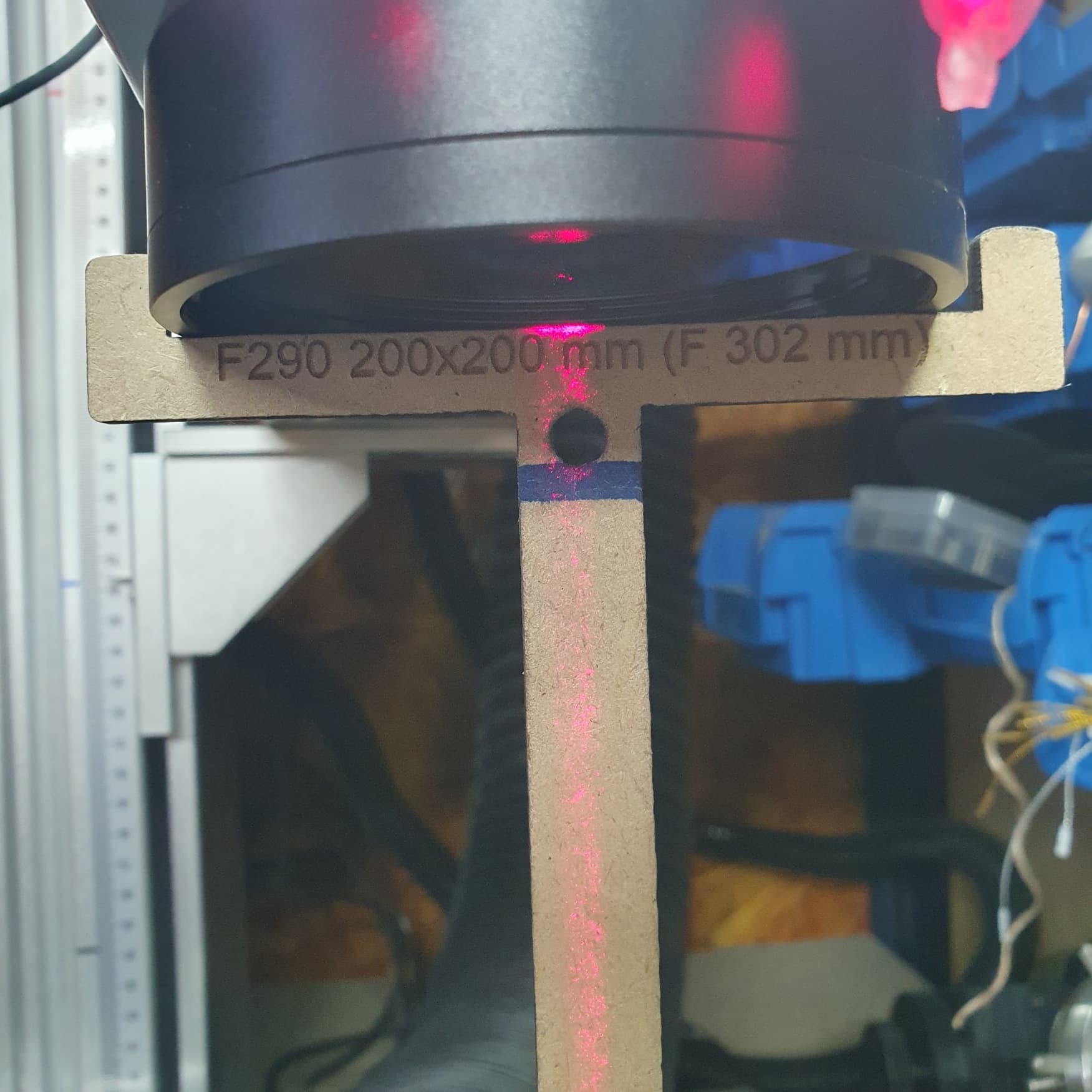
you can see that i have selected my mopa M7 60 watt witf F290 in the left on the scren ![]()
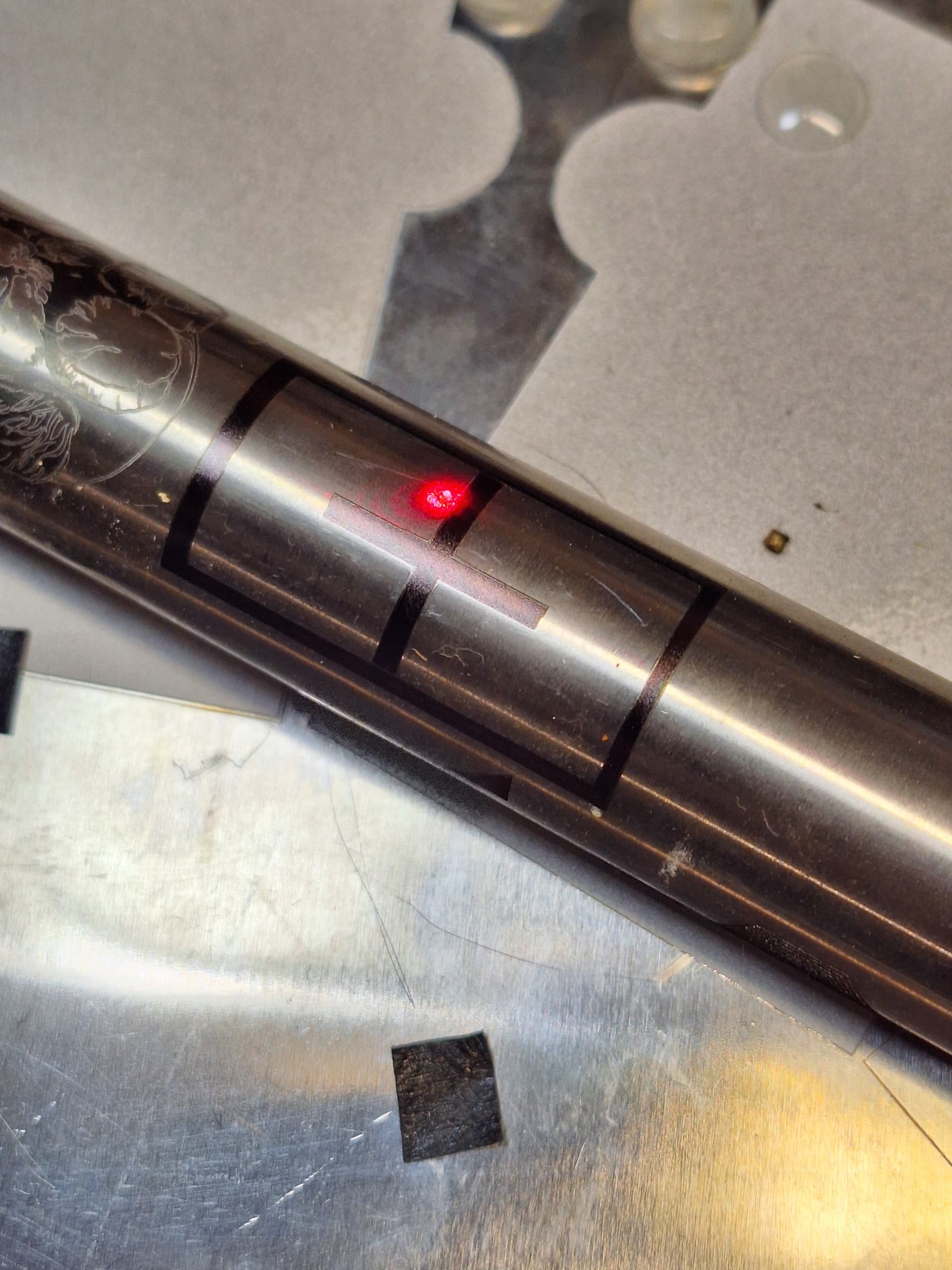
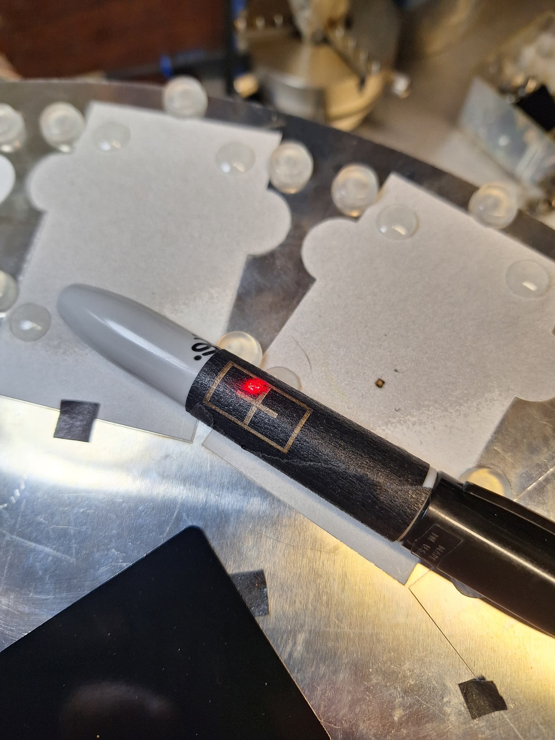
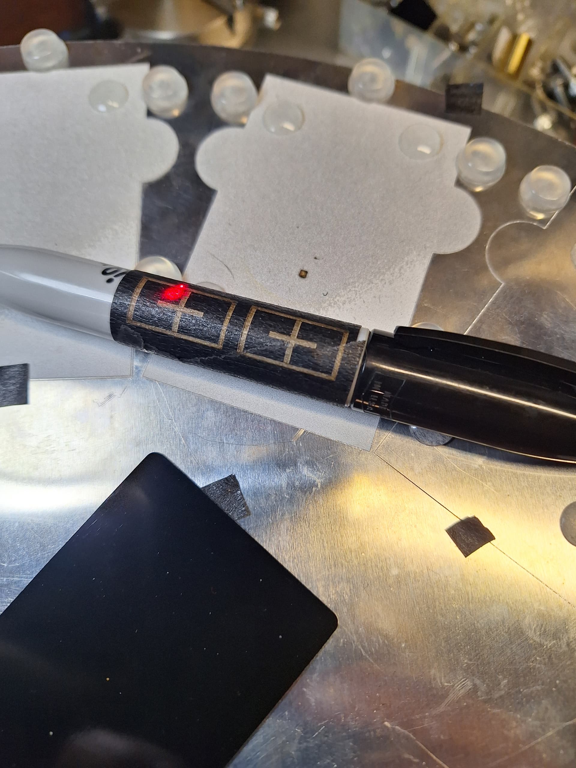
I have small cylinder objects to engrave
rotary is not enabled, i use a lot the cylinder correction on my fiber and
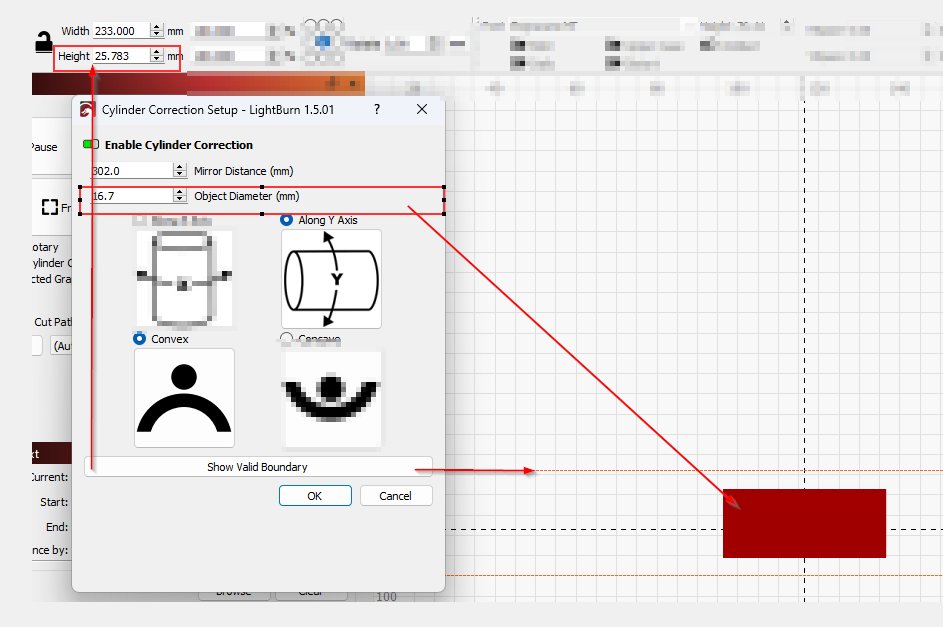
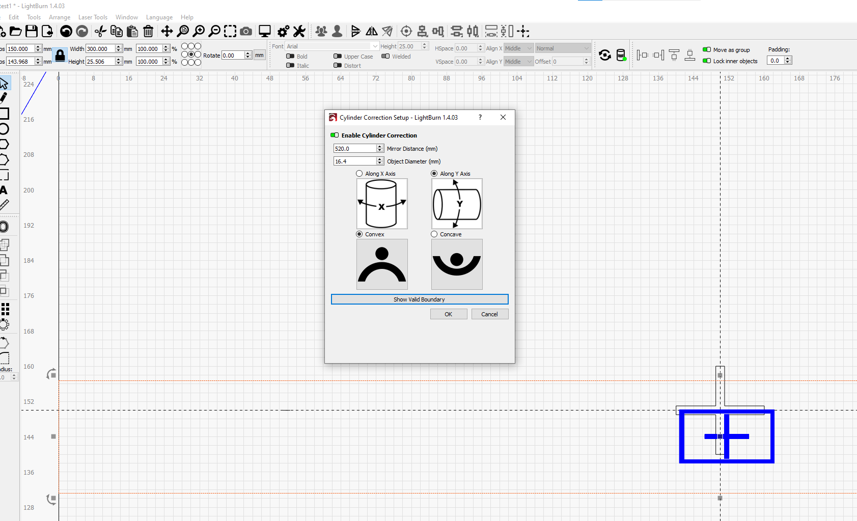
now i notisch that it isnt right. the cylinder is 16.7 mm and the output the corection tool was 24… and not even in center
Thanks for the clarification. I was confused because you posted this with “grbl”, “rotary”, and “bug” tags.
It’s not clear to me what you’re showing as the problem. You have labeled numbers but I don’t see how those are to be interpreted.
Can you please elaborate?
Also, can you upload the original .lbrn file for review?
A couple things. I think you are really pushing the limits. Did you try “Show valid boundaries” You might be outside that boundry.
Also, cylinder correction is more for things like bracelets or flask type objects (In my opinion) Things that have really large diameters that won’t roll in a rotary.
I’ve ran some tests, Mirror distance works best when measured to center of laser path. Probably about 400mm with a F=290 lens but you would have to focus and measure yourself.
In theory it should work on a pen but probably not the best tool.
Thnx for the answer so far guy. ![]()
I cant find a tag for galvo or fiber, zo thats why i use some other tags that sounds Familiar.![]()
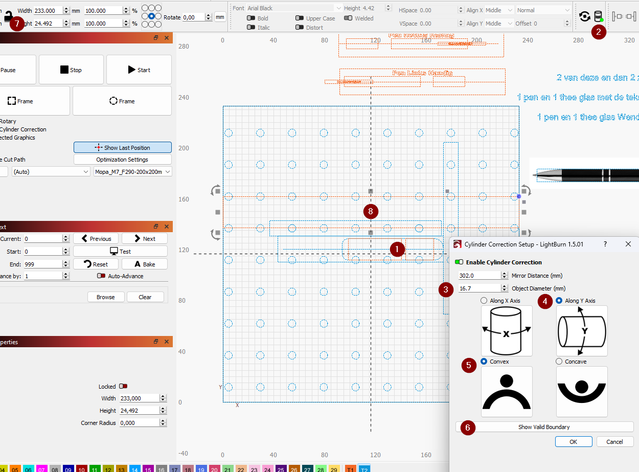
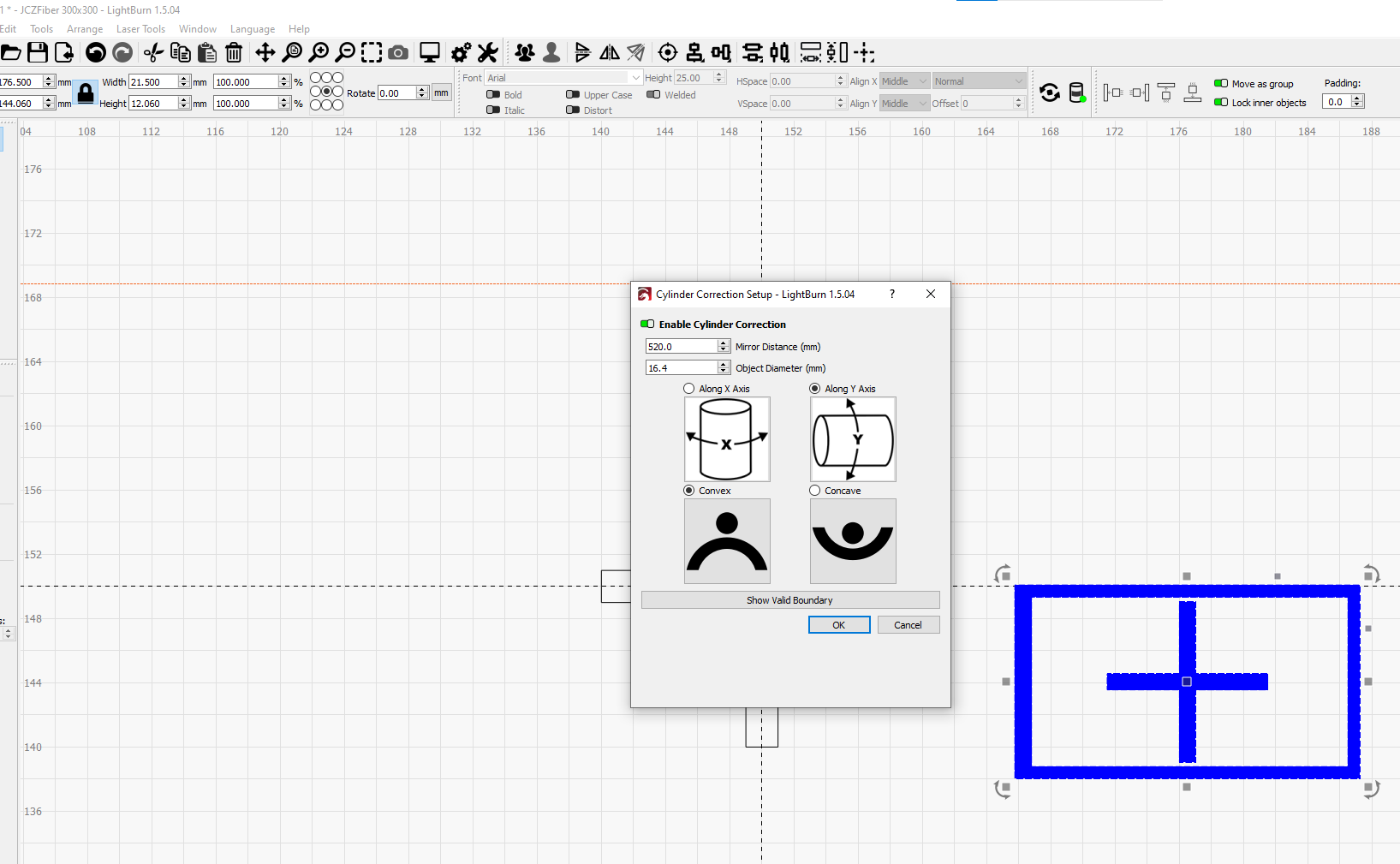
When i click show bondary [6]
The the boundry apairs in what i think the wrong spot [nr8] and way to big [nr7] my object is just 16.7 [nr3]
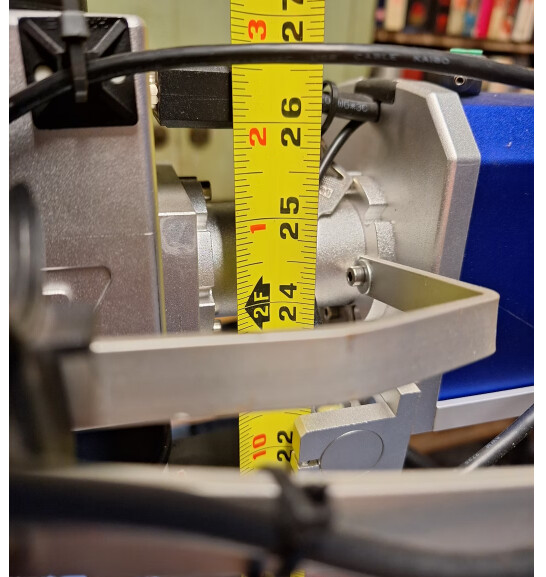
The mirror distance is perhaps wrong and i use my focal stick distance. Dosnt everybody ise focalsticks. Mirror distance is harder to messure ?
Thought i alway best have to use it with my galvo on cylinder objects to get the best result for out of focus.on the rounding…
Regards Edwin
Agree your boundary looks too big, like 25mm or so, 24.492 if that is what is selected. . There is a lot of stuff on your screen so I can only go by what you say.
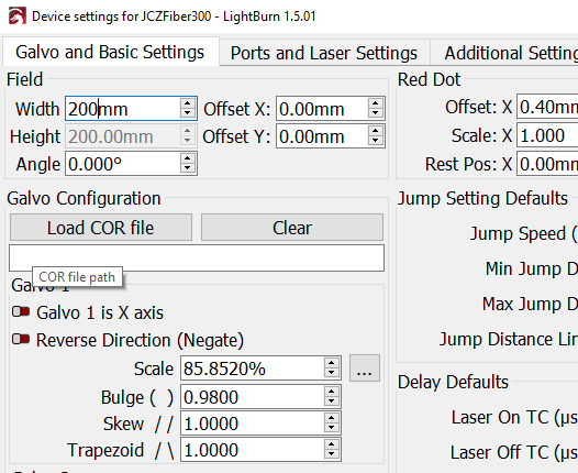
So starting over, with a 200x200 F=290 lens your screen should show 200x200 work area if everything set up correctly. yours is 233. Without cylinder, lens at focal stick height, does your laser burn correct scale? Have you calibrated this lens?
Yes all the lenses are perfected calibrated. the 200x200 is de ideal erea, the 233x233 is the max erea for the lens after calibration. same as F290 is called standard but my Focal stick is F302. Every lens and machine are always a bit different.
The numbers reprensent the staps i did.
step 1 is the object (perfume diffuser)
step 2 activate Cylinder correction
step 3 object diameter
step 4 selection
Step 5 selection
Step 6 show boundary
Step 7 Boundary diameter what LB created
Step 8 Boundary that LB shows
Though the steps made it easy, atleast in my head LOL
But also with bigger objects like glasses, when i use cylinder correction is not work fine for me and the show boundarys have always bigger diameter dan the object diameter.
I don’t understand “binnen” can you please find another word?
F-Theta length (290 in your case) being less then your focal stick (302mm) is not unusual. My case with 300X300 F=420 lens 450mm is my focus stick distance.
The mirrors are about 75-100mm above the lens, that is why measuring to center of path seems to give best results.
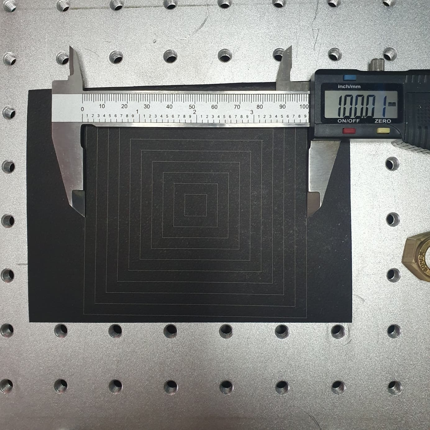
I don’t know why the “show boundary” is larger then the diameter I think you have something wrong in your calibration. Did you import a markcfg7 file from ezcad or did you use the LB utility to calibrate? If you burn a 100X100 square, what does it measure?
If you set the Width and Height to 200x200, burn a 100X100, what does it measure?
Binnen is bigger, auto correction is some time ![]()
My focal stick is from bottom lens to object.
My opinion, Thats the easiest way to use a stick.
I dont know how you use your stick and measures where ?
The calibrations and lines are correct.
In yhe beginning i used easycad files
But LB mess them up in 14.05 and had to recalibrate again. And now on 1.5x i use the calibration tool.
I even did a new lens correction in LB yesterday and use the 85/90% to correct its the same as i use the 100%
200 vs 233 dosnt matter
Stil the same problem with cylinder correction option.
I think its a software issue.
Dont pin yourself on the 200mm because thats the safe boudary of the lens. That dosnt mean you can use the full boundary of your lens and eccept some distortion depending of the object.
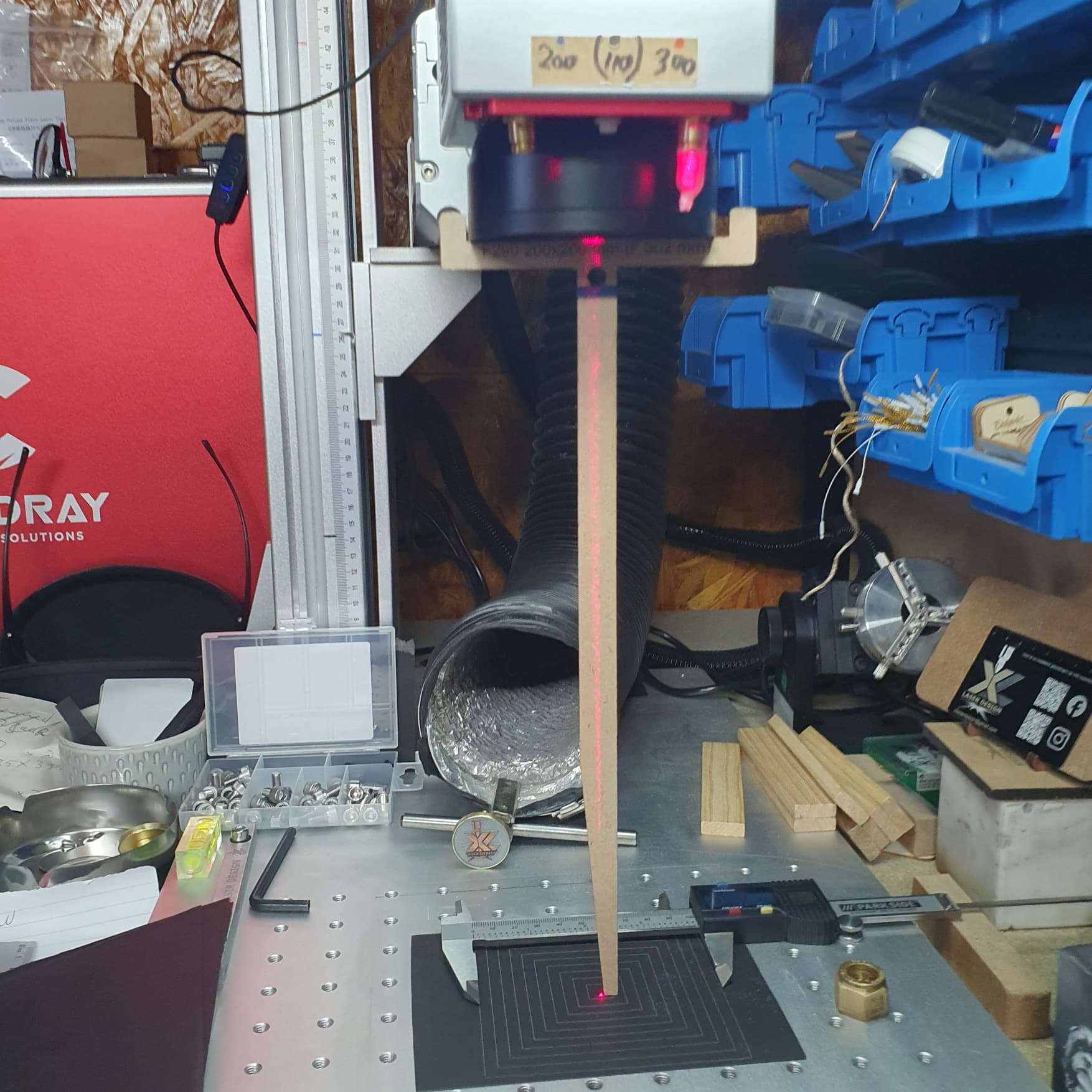
My 233mm line is also spot on
Show you the lines later from my test grid ![]()
Sometime you need just a little bigger space to engrave.
btw my settings from LB 14.05 are better then the LB 1.5 correction i tryed yesterday. the lens correction in LB 1.5 is not that great actually for what i can see and tested
I may not be much more help then, but if you wanted to post the file I would be happy to open up on my machine and try to replicate, in the name of science.
Your stick is fine, I was just noting for cylinder correction the “Mirror Distance” is greater then the stick by 75mm-100mm I determined by testing.
Measuring to the center of the pathway gave me the best results.
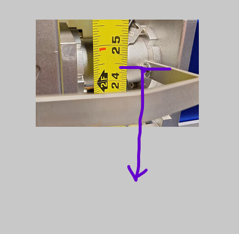
Mirror distance
its not the file.
The show boundary looks with new file center but now even bigger diameter.
While the red object is stil 16.7.
Not using cylinder correction anymore untill the next update.
Then i trying it again and will see.
Atleast im sure its nog my settings now ![]()
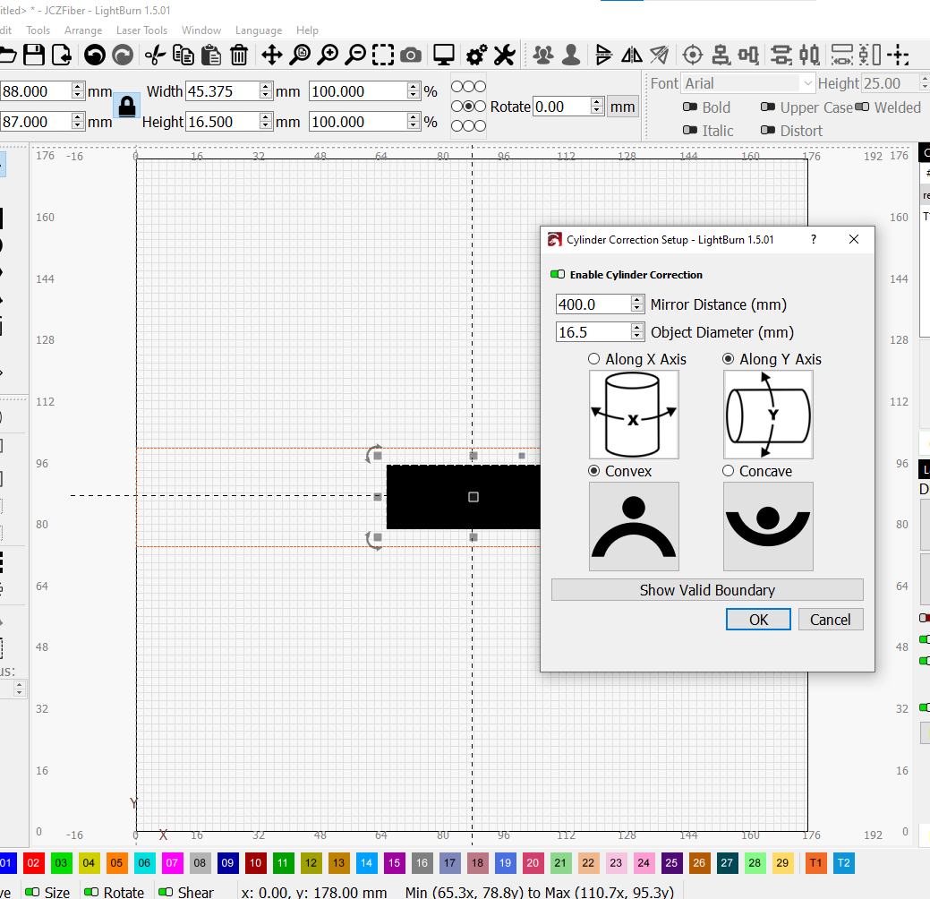
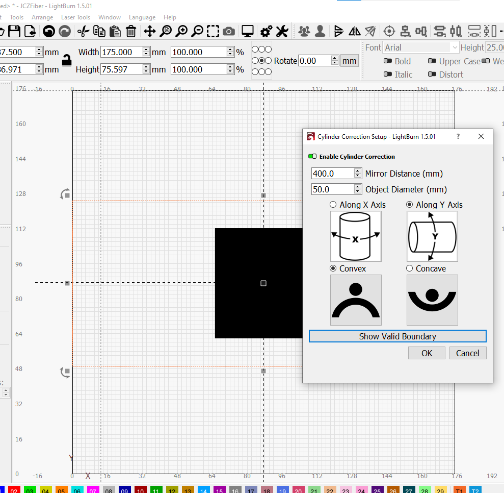
Convinced me. I did 16.5, valid boundary about 25mm. Did 50, valid boundary 75.
EDIT: Not convinced after testing before and after update. See below post.
This is with LB 1.5.01
I didn’t burn anything because I have the rotary table set up right now, and LB 1.4x on the machine I use for the laser (and have used for cylinder correction in the past,) but seems like a bug to me. I’ll try before and after an update.
The show valid boundary is the area in the workspace can be placed, not the limit on the object.
Tested—
LB 1.4.03: Placed a 1" diameter object and ran a rectangle, came out good. Then ran a 16.4mm diameter pen, rectangle came out good.
Updated to 1.5.04
Ran same rectangle came out identical.
Thanks for testing also.![]()
But If that boundary does not give the correct diameter, what is the added value of the cylinder correction tool, I wonder. If we already measure the diameter of the object, the correction tool is useless ?
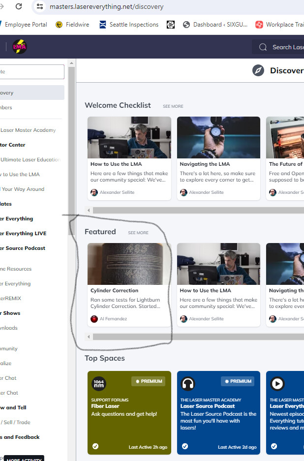
The boundary shows the area that the object can be placed in the work area. The correction corrects for the curvature. Does a good job of it. I did an article on cylinder correction on the Laser Master Academy a few weeks ago, you should check that out, and the link I provided above to the documentation does a good job of explaining it. Maybe you are expecting it to do something different then intended? Links don’t work from here to LMA but here is where it is if you want to check it out.
i know the LMA there where nice with the early videos. now days to mutch talk and interviews.
But like the lma for sure.
i watch this one and followed the courses

for bigger object is the correction ok. ik guess
Worked for me on the 16.4 mm pen. I use it mostly for flasks.
This topic was automatically closed 30 days after the last reply. New replies are no longer allowed.