Depth maps that claim 16-bit and aren't — how to spot them before you slice

Something I kept running into with 3D Sliced Image work, and a free tool I wrote to deal with it. Posting the mechanism first because it’s worth knowing whether or not you want the tool.

The problem

A greyscale depth map can declare 16 bits per sample and contain only 8 bits of real depth information. Three ways this happens, all common:

  • Byte replication — an 8-bit value widened as v × 257. Every level lands on a multiple of 257. Header says 16-bit, file is twice the size, depth resolution unchanged.
  • High-byte shiftv × 256, low byte left at zero.
  • Quantised ladder — a 10-bit or 12-bit source stretched across the 16-bit range. Subtler, and the one that gets missed.

Nothing in the normal chain flags any of it. Image viewers show a smooth ramp. Photoshop reports 16 bits/channel because it’s reading the header. LightBurn imports it without comment, correctly — it has no reason to audit your file. The result shows up as terracing on the workpiece at pass counts that should have been fine.

AI relief generators produce these constantly, because their output stage writes 16-bit PNG regardless of what the model actually generated.

Why it matters here specifically

Number of Passes is the slice count, so it’s the real depth resolution. If the file carries 256 usable levels, raising the pass count past that buys nothing — you’re paying time for steps the data can’t fill.

Worth knowing too: LightBurn’s docs note that a 24-bit depth map is three 8-bit channels and displays as 8-bit. So grey data saved as RGB isn’t just wasted bytes on this path — it can cost precision the file appears to have.

The tool

DepthView counts what’s actually in the pixels. Free, MIT, no signup, single file, Windows/Mac/Linux — nothing to install.

GitHub - LeeGillie/DepthView: Depth map inspector: reports what a depth map actually contains, not what its header claims. Bit-exact decoding, imposter detection, and a software-rendered 3D relief preview. · GitHub

Typical output screening a folder:

OK    16bit  56,299 levels  step 1     coin-front.png
FAIL  16bit     256 levels  step 257   coin-back.png
FAIL  16bit   1,024 levels  step 64    logo-relief.png

step is the GCD of the gaps between occurring levels. Genuine data gives 1. A step of 257 or 256 is byte-widening; 64 is a 10-bit ladder. Exit code 1 when anything is flagged, so it drops into a batch script.

It also reports unused headroom (a map spanning 267–63,271 wastes passes at both ends), pure-black and pure-white pixel counts where depth has already been clipped away, and it renders a lit 3D preview with a terracing control you can set to your pass count.

The PNG decoder is hand-written rather than platform-supplied, because WIC, CoreGraphics and GDK all quietly hand back 8 bits for a 16-bit PNG — which would make the tool useless for the one thing it’s for. All bit depths, all colour types, Adam7, plus Netpbm and PFM.

Scope, so nobody downloads it expecting the wrong thing

It inspects and previews. It does not generate or export files — no invert, no remap, no quantise-to-pass-count, no .lbrn2. That’s roadmap, not shipped. And 3D Sliced Image mode is galvo-only, though the analysis applies to greyscale relief on any machine.

What I’d like back

If it reports something you believe is wrong about one of your files, please tell me — that’s the most valuable thing I can hear. The last fix came from exactly that: two genuine 16-bit maps of mine were being flagged when they shouldn’t have been, and no synthetic test case could have caught it, because a fixture with a known answer can tell you a measurement is wrong but never that a correct measurement is carrying the wrong emphasis.

Mac and Linux reports also welcome. Automated builds prove it compiles and analyses identically on all three platforms, but the file dialog, drag-and-drop and clipboard paste need a real person on a real machine.

4 Likes

For someone working with images a lot, this is really good information. Thank you for the time you took to research and report this. It might help explain why we do not get the expected results.

With the birth of 3D in MillMage, and Fiber lasers I don’t have, this is truly needed information.

Nice explaination. I don’t understand what a higher bit density actually helps you with lasing things.

I use 3dslice a lot with the fiber.

So to reasonably use this with 16 bits would require a pass for each value or 65,536 passes. I’d be dead waiting for it to complete as most 8 bit 256 pass jobs require one to two hours.

So what is the advantage of a 16 bit depth map… some of it has to be thrown away…?

I’d like to understand where you’re going to make this useful to me going to 16 bits?

:grinning_cat:

You’re right, and thank you — that’s a correction worth having.

I’d been treating “is the file really 16-bit” as the headline question for the LightBurn path, and Oz’s description of the mechanism makes clear it mostly isn’t. If each pass is thresholded to a 1-bit image and anything past 256 passes duplicates layers, then a 16-bit source buys no extra depth resolution through 3D Slice. My README said otherwise; I’ve corrected it and credited you.

So let me answer the real question — what is useful here, given a hard 256-level ceiling.

Not “do I have 65,536 levels”, but “can I actually reach 256”. Most depth maps can’t, and the reason is range rather than bit depth. If your map occupies 60% of its range instead of all of it, it reduces to roughly 154 distinct levels. Run 256 passes on that and about a hundred of them duplicate a slice that already exists — time spent, no material removed. DepthView reports range utilisation and unused headroom, which is precisely that number. I’d been burying it as a supporting stat; it should be the headline, and I’m moving it.

Clipping is the same story from the other end. A big flat black region means the depth was crushed upstream before you got the file. Those aren’t slices, they’re one slice repeated, and no pass count recovers it. It counts those pixels explicitly.

And some files genuinely hold fewer than 256 levels while advertising 16-bit — that one still bites on your path, because you can’t fill passes with levels that aren’t there.

Where 16-bit does still earn its keep — and I should have framed it this way from the start — is as working precision, not output precision. Same logic as editing photos in 16-bit and exporting 8-bit. If you resize, rotate, blur, level-adjust or combine maps before slicing, an 8-bit source bands as it goes and a 16-bit one survives to the reduction. Hand an untouched file straight to 3D Slice and you’re right, it makes no difference.

You’ve also just written my next feature. The number that actually matters to a 3D Slice user is “after reduction to 256, how many distinct slices does this file produce, and how many of my passes are duplicates?” Everything needed is already computed; it’s a framing problem. That’ll be in the next build.

Given you use 3D Slice a lot with the fiber — if you run a few of your own maps through it and the range utilisation numbers look off against what you see on the material, I’d like to know. That’s the kind of thing I can’t test from here.

1 Like

Implemented and released — v1.1.0 is up.

You were right, and it turned out to be the most useful thing anyone’s told me about this tool. I’d been treating “is the file really 16-bit” as the headline question for 3D Slice users, and Jason’s description of the mechanism makes clear it mostly isn’t. If each pass is thresholded to a 1-bit image and anything past 256 duplicates layers, a 16-bit source buys no extra depth resolution on that path. My README said otherwise. It’s corrected, and credited to you.

So I made it answer the question that survives: how many distinct slices does this file actually produce, once it’s been reduced to 256 levels?

Two files from my test set:

  17,463 levels  ->   88 usable slices   (167 more recoverable by remapping)
   7,814 levels  ->  238 usable slices   (near optimal)

The first holds more than twice the levels and produces a third as many depth steps, purely because it occupies about a third of its range. That inversion is the whole point — the raw level count told you nothing useful, and the slice count tells you what to set Number of Passes to.

The report now says it plainly:

SLICING (through a 256-level slicer, e.g. LightBurn 3D Slice)
  Usable slices     88
  Suggested passes  88   (more than this duplicates layers)
  Recoverable       167 more by remapping to full range (255 total)
  At a given pass count:
      64 passes        64 distinct
     128 passes        88 distinct, 40 repeating an existing slice
     256 passes        88 distinct, 168 repeating an existing slice

One caveat I’d rather state than have found: I model the reduction as proportional rounding into 0–255, which is the ordinary way an image is taken to 8 bits. If 3D Slice truncates instead, the counts shift slightly. It’s documented in the code as an estimate rather than a claim about LightBurn’s internals — and if anyone can tell me the actual behaviour, it’s a one-line change.

Releases · LeeGillie/DepthView · GitHub — v1.1.0.

If you run a few of your fiber maps through it, the number I’d be most interested in is whether the suggested pass count matches what you’ve arrived at by experience. That’s the check I can’t do from here.

Thanks again — it’s a better tool than it was this morning, and that’s down to you asking the awkward question rather than letting it go.

“3D Slice” for galvos in LightBurn used to be internally 8-bit, but that 8-bit pathway was updated with support for 16-bit images with the release of LightBurn 2.1 (see the release announcement here or the LightBurn online documentation). I know I, for one, was very much looking forward to that update (but not quite as much as I’m looking forward to the full release of MillMage’s Pro features).

I would not expect many people to attempt to do a job with a full 64 kibislicles (or at least not complete it… or at least not try it a second time), but even with a much lower number of slices, starting with a 16-bit depth map can be a great improvement. If you have large areas of smooth gradients and want to decrease posterization, you certainly want to work with true 16-bit files.

You’re right, and thank you — I should have checked the version before rewriting anything.

I’d taken the earlier quote about the 8-bit thresholding path at face value without noticing it predated 2.1. The current docs are unambiguous: “As of LightBurn 2.1, LightBurn support 16 bit depth maps”, and “if you plan to run more than 256 passes, a 16 bit image is better.” So my original position was right, my correction was wrong, and this one’s on me for not going to primary sources.

The useful outcome is that the tool no longer assumes any ceiling. It reports what a file resolves at whatever pass count you’re running:

  passes    depths   wasted        passes    depths   wasted
      64        61        3            64        22       42
     256       238       18           256        88      168
    1024       948       76          1024       347      677

  genuine 16-bit, full range     16-bit using a third of its range

The left file keeps resolving new depths well past 256, which is precisely your point about posterisation on smooth gradients — that only works because it really holds 16 bits. An 8-bit map widened to 16 stops dead at 256 however many passes you throw at it.

The right file is the one I find more interesting: it holds more than twice the grey levels and resolves a third as many depths, purely because it wastes most of its range. Same fix either way — reclaim the range — but you’d never see it from the header.

Both corrections shipped. Being wrong twice in public in one thread is a bit steep, but the tool’s better for it.

1 Like

The documentation states pretty clearly to me that it’s real use is for >256 passes. And only because it can make more detail the with the extra passes.

As of LightBurn 2.1, LightBurn support 16 bit depth maps. If you plan to run more than 256 passes, a 16 bit image is better, as it can contain more than 256 shades of gray. You can see the bit depth of an image that’s been imported into LightBurn by selecting only that image and checking the status bar, as shown in the image below.

The only way to get those extras is to increase the number of ‘slices’.

At least that’s how I read it :man_shrugging:

:grinning_cat:

Whatever the documentation may imply, the math makes a very strong case that for smooth gradients, 16-bit depth matters even for smaller slice totals. For example, if you have a full-range 8-bit depth map (256 levels) and you want 200 slices, each slice is a value step of about 1.28. If you have full-range 16-bit depth map (65,536 levels) and you want the same 200 slices, each slice is a value step of about 327.68. (The actual image pixel values are integers, of course.)

When you try to distribute the values evenly across slices, you run into the limits of simple integer arithmetic. With the 8-bit depth map, 144 of the slices will each cover 1 step of the 256 values, and 56 of the slices will cover twice that much. With the 16-bit depth map, 136 of the slices will each cover 328 steps of the 65,536 values, and the remaining 64 will cover 327 steps. The absolute value of the difference is still just 1, but the ratio of that error to the signal is drastically different.

Having some of your slices cover twice the range of the others is obviously less desirable than having some of your slices cover 327/328ths of the others. Even for this basic example with only 200 slices, smooth gradients in your depth map will look better if you have a full-range 16-bit source.

(And now I’m having flashbacks to low-bit-depth airshow photos with crystal clear blue skies.)

Nathaniel, that’s the argument I was missing, and I spent an evening checking it because this thread has already corrected me once and I’d rather be corrected twice than wrong after being told.

Your arithmetic reproduces exactly. Full-range 8-bit at 200 slices: 144 bands covering one value, 56 covering two. Full-range 16-bit at the same 200 slices: 64 bands of 327 and 136 of 328. Same absolute error of one, completely different relative error — as you said.

What surprised me is that it’s worse than your example suggests. I swept every slice count from 2 to 256:

        8-bit source              16-bit source
slices  band widths   ratio       band widths   ratio
   100     2..3      x1.50          655..656   x1.0015
   150     1..2      x2.00          436..437   x1.0023
   200     1..2      x2.00          327..328   x1.0031
   255     1..2      x2.00          257..258   x1.0039
   256     1..1      x1.00          256..256   x1.0000

With 256 levels the only slice counts that divide evenly are the powers of two — 2, 4, 8, 16, 32, 64, 128, 256. That’s 8 out of 255. Meanwhile 127 of 255 give a 2:1 spread, where some terraces come out twice as wide as their neighbours. With 16 bits, nothing in that range is worse than 1.004.

So it isn’t a “>256 slices” concern at all. Unless you happen to land on a power of two, an 8-bit source gives uneven terrace spacing at basically any slice count. The depth count looks perfectly healthy — ask for 200 slices, get 200 distinct depths — but the mapping from grey level to depth has a sawtooth in it, and on a smooth dome that’s exactly the banding you’re describing from the airshow photos.

@jkwilborn — I think this is the bit the documentation leaves out rather than gets wrong. “If you plan to run more than 256 passes, a 16 bit image is better, as it can contain more than 256 shades of gray” is true, and it’s about count. Nathaniel is pointing at spacing, which is a separate axis and bites well below 256. Your reading of the docs is right; the docs just aren’t making the second point.

I’ve added it to DepthView as a measurement, because it turns out to be the second thing an imposter costs you and I wasn’t reporting it. Same picture, two encodings:

genuine 16-bit
  passes    depths   wasted   headroom   band spread
     200       199        1        199   327..328 x1.00

8-bit ladder inside a 16-bit container
  passes    depths   wasted   headroom   band spread
     200       199        1        199   1..2 x2.00

Identical depth counts. It’s measured against the ladder the file actually carries rather than the container it declares, so an imposter lands on the same row as an honest 8-bit file — which is the whole point of the tool, except that I’d only been counting depths and not measuring spacing.

Thanks to you both. Nathaniel, that’s twice now.

DepthView 1.2.0 — it now fixes what it finds

The version I posted about earlier could tell you a depth map was wrong and then leave you there. That always felt like half a tool. 1.2.0 is the other half.

Download: Release DepthView 1.2.0 · LeeGillie/DepthView · GitHub

Windows, macOS and Linux, x64 and ARM. One file, nothing to install, no runtime to add first — the .NET runtime is inside the executable. Free, MIT licensed, and the binaries aren’t code-signed, so the release page explains what your OS will say about that.

What the tuning window does

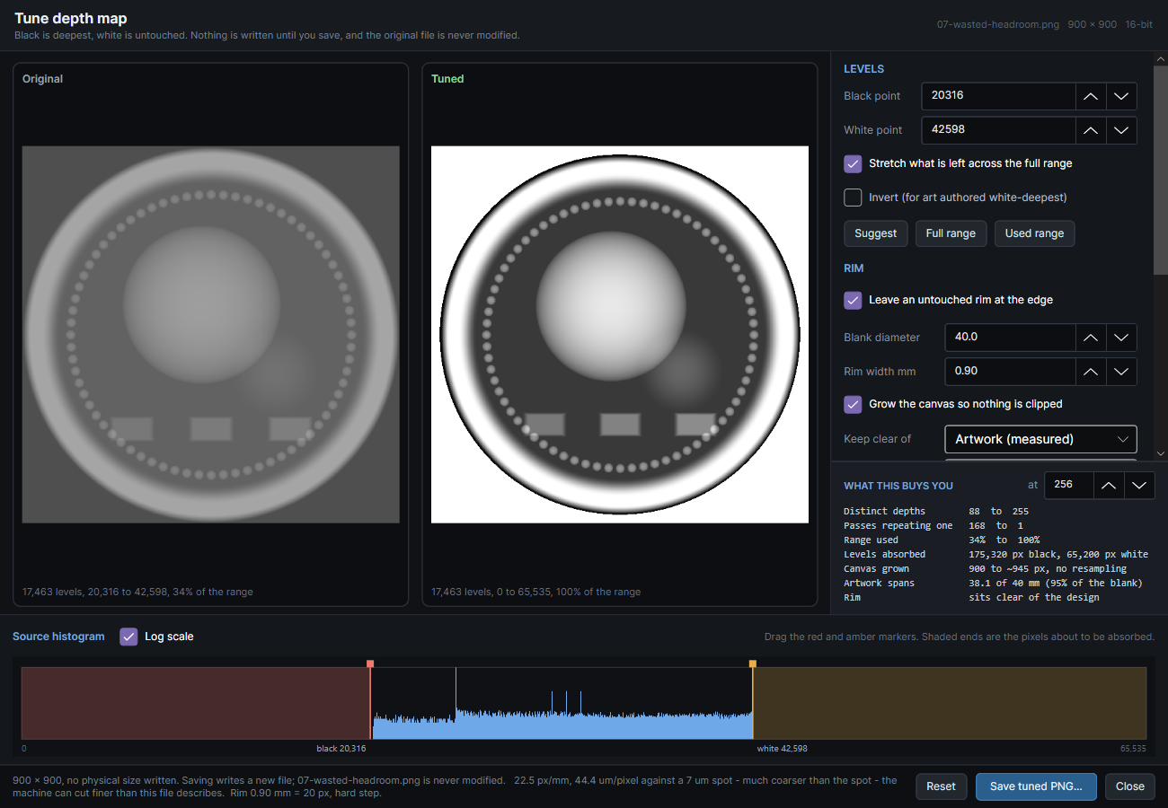
Load a map, press Tune…, and you get the original and the corrected version side by side with the source histogram underneath. Drag the two markers on the histogram:

  • Everything at or below the black point becomes one uniform full depth. That’s how a noisy floor stops engraving mottled and starts coming out as a clean polished plane.
  • Everything at or above the white point is left untouched — zero passes, bare metal.
  • What’s left is stretched to fill the range, and the shaded ends of the plot show you exactly which pixels you’re giving up to get that.

Every number updates as you drag. The panel answers the only question that matters: at the pass count you intend to run, how many distinct depths do you actually get, before and after.

On one of the bundled samples, that’s this:

  levels          black 20,316, white 42,598, stretched
  flattened       175,320 px to pure black, 65,200 px to pure white
  depths @ 256    88 -> 255   (wasted passes 168 -> 1)
  range use       34.0% -> 100.0%

88 distinct depths to 255, at the same 256 passes. 168 passes that were re-cutting a depth already cut, reduced to one. That map wasn’t broken — it just only used 34% of its range, and nothing tells you that by looking at it.

For coin blanks

Rim geometry is entered in millimetres, because that’s how a rim is actually known — with calipers, not as a percentage:

DepthView --tune coin.png --blank 40 --rim-mm 0.9 --fit --outline

That leaves the raised rim untouched, and if your artwork runs past it you’re told what it costs — the percentage of the design that overlaps and the scale that would clear it.

--fit is the part I’m most pleased with. When artwork runs past the rim the obvious fix is to scale it down, and that’s the wrong fix: scaling interpolates, and interpolation invents grey levels that were never in the file — the exact fault this program exists to detect. So instead the canvas grows and the original pixels are copied into the middle of it, byte for byte, nothing resampled. The blank is still 40 mm either way, so the same artwork just spans fewer of its millimetres, and it arrives at a finer effective resolution than before:

  fitted          canvas grown 900 -> 942 px so the design clears the rim; no pixel resampled
                  the artwork now spans 38.2 mm of the 40.0 mm blank, at 23.6 px/mm

Aligning it to the blank

This one took me a while to work out. LightBurn frames three ways — Bounds, Hull and Contour — and an image is a rectangle to all three, whatever is drawn inside it. A round design in a square PNG always frames as a square, and nothing you can do to the pixels changes that, because the framer never looks at them.

So --outline writes a true-size SVG alongside the map: a circle at the blank’s diameter, a second at the edge of the engraved area, and a centre mark. Then:

  1. Import it alongside the map — both are in millimetres and the PNG carries its own physical size, so they land in register.
  2. Put the circles on a tool layer (T1). Tool layers never go to the laser.
  3. Turn Frame off for the image layer in Cuts/Layers. This is the step that matters — leave it on and you get the box back regardless.
  4. Frame with Hull or Contour. Bounds is a rectangle by definition.
  5. The pointer traces the circle. Line it up with the rim.

Calibrating to your machine

--calibrate writes a coupon sized to your blank: a depth wedge, ramps at known wall angles, and a comb of shrinking gaps, plus a worksheet to fill in at the bench. Engrave it once per machine and material, measure it, and you know the depth your settings actually reach, the steepest wall your machine will hold, and the finest detail its spot can resolve.

I’ll be honest that I haven’t cut mine yet — brass and stainless are queued. Until I have, some defaults in the tool are honest admissions rather than knowledge. The rim ramp defaults to none for exactly that reason: I don’t yet know what wall angle a Lumos Ultra holds at depth, and I’d rather ship “I don’t know” than a number I made up.

Everything is a measurement, not a claim

Every tuning run re-reads the file it just wrote and analyses it from disk as if a stranger had sent it. If what the tool predicted and what it measures ever disagree, the prediction is what’s wrong. The same applies to the window — the numbers you watch while dragging come from putting the whole histogram through the same arithmetic, so they’re exact for the entire image rather than sampled from a preview.

And nothing anywhere writes over your original. Every path produces a new file.

What it still won’t do

It won’t tell you your power and speed. It has no idea how your material ablates — that’s what the coupon is for. It doesn’t resample a map to a target DPI yet, which is a real gap if your art is 1024 px on a 40 mm blank. And a preview is a preview: it shows form and banding, not slag, heat accumulation or edge rounding from beam width.

Thanks to everyone in this thread. The band spread column exists because Nathaniel Klumb argued with me and turned out to be right, and the 16-bit section of the README is correct because he caught me conceding a point I hadn’t checked the version on.

1 Like

There are a few problems with the conclusions here.

The biggest one is calling repeated slice masks “wasted passes”. If two consecutive 3D Slice passes use the same mask, the second pass still fires and removes more material. It does not add another distinct slice boundary, but it still contributes to the physical depth. A repeated mask is not the same thing as a wasted laser pass.

The same applies to stretching a map from 34% to 100% of the available range. That is not simply recovering wasted resolution. You are changing the mapping between grey value and pass count, which changes the vertical scale and offset of the relief. If that limited range was intentional, forcing it to the full range changes the intended engraving rather than “fixing” it.

The file analysis itself is useful. The problem is taking digital properties of the image and treating them as if they directly describe the physical material ablation.

1 Like

Finn — you’re right on both counts, and the second one is the more serious of the two. I went and worked it through properly rather than argue.

On repeated masks: yes. I checked what those 256 passes actually do on that sample, and “wasted” is a bad word for it because it turns out to describe two completely different things that I’d lumped together.

passes   1..89    every artwork pixel is in the mask. The laser fires, material
                  comes off - it just comes off everywhere equally. That's a uniform
                  recess 89 passes deep. Depth, but no form.

passes  90..176   masks shrink. This is where the relief is actually made.
                  87 passes carrying the entire image.

passes 177..256   nothing in the map is dark enough to be in the mask at all.

So of the 168 I was calling wasted, roughly 89 are cutting real material that produces no relief, and roughly 80 have nothing in the mask. Whether LightBurn skips an empty pass or runs it, I don’t actually know. Either way, calling the whole 168 “wasted” implies an idle laser, and that’s not what’s happening. A repeated mask adds depth. It doesn’t add a distinguishable level. Those are different claims and I was making the wrong one.

Your second point is the one that actually undercuts my headline, and I want to be plain about it rather than bury it.

I’ve been describing stretching a map from 34% to 100% as recovering wasted resolution. It isn’t. Work it through: that map’s relief occupies 87 passes of depth and resolves into 88 distinct levels. That’s 1.01 levels per pass of relief depth — the theoretical maximum. You cannot fit more levels into a relief than you have passes of depth to put them in. Nothing is being wasted.

What stretching actually does is make the relief roughly three times deeper, and it gets more levels because it is deeper. Levels per unit of depth are identical before and after. If that 34% range was deliberate — somebody wanting a subtle shallow relief — then my tool isn’t fixing their file, it’s overriding their intent by a factor of three and calling it a correction. And nothing in the file says which it is.

On your third point I’d push back a little, but only a little. The numbers have stayed on the right side of that line: nothing in DepthView claims to know depth in millimetres, --depth-mm explicitly changes no pixels and only reports the geometry the settings imply, and the whole reason there’s a calibration coupon is that the file cannot tell you how your material ablates. The rim ramp defaults to none precisely because I don’t know what wall angle a galvo holds at depth and wasn’t willing to invent one.

But the language absolutely did cross that line. “Wasted passes” and “fixing” are physical claims dressed up as file analysis, and you caught them. The measurements were careful and the words around them weren’t.

So, what I’ve changed. All of it is in 1.2.1, which is up now — no new features, it exists purely because 1.2.0 said two things that weren’t true:

1. The word “wasted” is gone. Not softened — removed. There is no column called that any more, anywhere in the report, the window or the docs.

2. The stretch is reframed as what it is. It’s no longer described as a repair. It’s a decision about how much of your available depth the relief uses, and the tool now says so outright: more depths because it is deeper, levels per unit of depth unchanged, worth doing if the narrow range was an accident and worth leaving alone if it wasn’t. The warning that used to fire merely because stretching would add depths doesn’t fire any more — that was the tool calling a design decision a defect.

3. Reporting the split instead of the single number. The table now shows, for each pass count, how many passes form the relief, how many have every engraved pixel in the mask, and how many have nothing in it. On that sample at 256 passes: 87 relief, 90 uniform, 79 empty. They sum to the pass count.

I nearly wrote here that you’d therefore get an identical result from 176 passes, and I’m glad I checked before posting it, because you wouldn’t — the pass count is what sets the threshold spacing, so running fewer passes redistributes all of them and gives a shallower relief. The 79 empty passes can’t simply be dropped. What’s true is narrower: 79 of your 256 have nothing in the mask, and whether LightBurn skips them or runs them empty I don’t know.

4. README, release notes and the sample docs swept for anywhere else file properties were written as if they described material behaviour. The report itself now spells out that a large uniform count is not automatically a fault — it means the design sits in a pocket, which is sometimes exactly what was wanted, and the useful question is whether you asked for it.

Here’s the new table on that sample, for reference:

  passes   depths   uniform   relief   empty   stretched   band spread
      64       22        22       22      20          64   348..349 x1.00
     128       45        45       43      40         128   174..175 x1.01
     256       88        90       87      79         255   87..88 x1.01
    1024      347       358      349     317       1,014   21..22 x1.05

None of this touches the imposter detection or the band spread work, which are both genuinely about the file and stay as they are.

Third time this thread has corrected me and third time the tool comes out better for it. Much appreciated — blunt and specific is far more use to me than polite and vague.

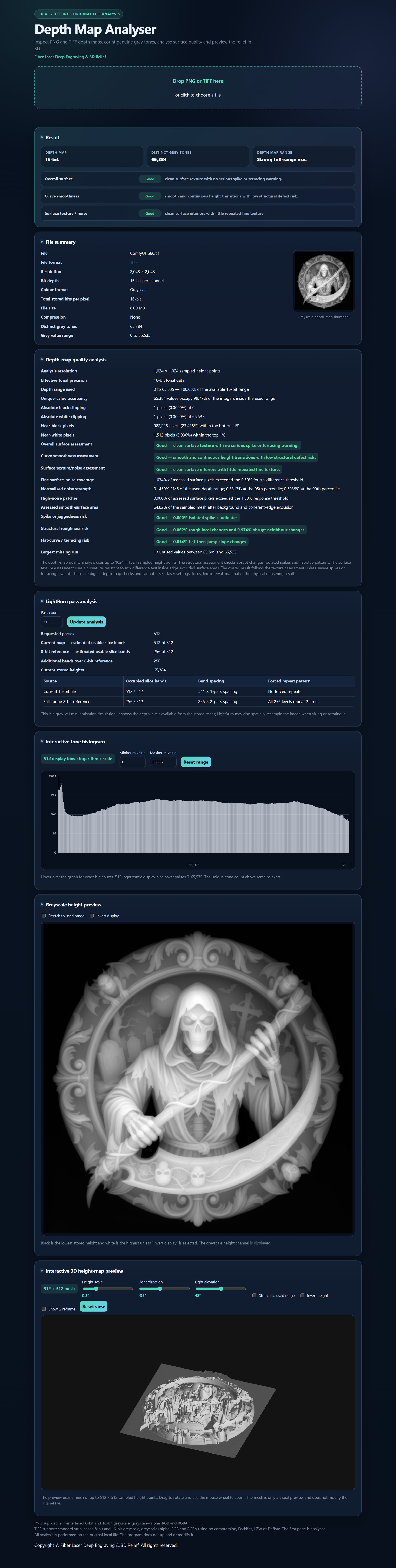
This is more the kind of depth-map analyser I find useful myself. Unique Download Link | WeTransfer

It still checks the basics bit depth, actual grey levels, tonal range and whether 8-bit data has simply been stored in a 16-bit file. but it also analyses the height map itself.

It looks at curve smoothness, surface texture/noise, isolated spikes, abrupt height changes and terracing, and gives you an interactive 3D preview so you can actually inspect the relief geometry. It also reports clipping, tonal-range use and LightBurn slice-band behaviour without assuming that a narrow range is automatically a defect.

You have lots of things that make your idea questionable. Each pass (slice?) represents a bit value. As far as I know, these ‘slice’ data sets are not exported by Lightburn, so I question your data sets origin.

This is how Oz advised how the 3d slice actually operates. This is from the 8 bit days, however the basic operation doesn’t appear to have change.

With 3D Slice, each pass is thresholded to the current threshold value, and the result is run as a 1-bit image. If you use 256 passes you get exactly one pass per gray-level in the image. Every pixel at or below brightness 255 for the first pass, every pixel at or below 254, then 253, and so on.

If you choose 128 passes, you get every pixel at or below 254 for the first pass, then 252, then …

It “clusters” the layers together into batches if you use fewer than 256 passes, and will duplicate some layers (with even spacing) if you use more than 256. 384 passes would duplicate every 2nd layer. 512 passes would duplicate every layer.

You statement that 200 passes covers the whole range is mathematically incorrect. If you want every level of the 8 bit pattern that 3d slice uses, you need to make 256 passes. What you want me to believe is that you can represent 256 values with only 200 passes? I can still do 8 and 16 bit math and know this doesn’t work. Something in your investigation or process is incorrect.

If you have a 16 bit image, and you exceed the 256 pass it will then interrogate steps in between, using the data it needs, which adds detail.

Such as you are doing 512 passes, you’ll get a more precise replication as it’s using 9 bits instead of only 8, but you have to make 512 passes, one for each bit value. Next up is 1024 passes, requiring 1024 passes where if uses 10 bits.

You have to increase the passes to use more than an 8 bit value.

I believe you’re missing how this works. More detail, more passes, it’s pretty simple.


Haven’t examined the 3d map software you claim to use, but if you’re this far off how it works I’m suspicious with any tools you’ve created. Especially for a fiber.

If I’m wrong here, I hope one of the Lightburn people will step in an clarify.

As far as I can tell, I don’t know if the extra bit or two is worth it. Mine, with 256 passes, takes almost two hours or more to run, doubling it for a single bit, will double the required job time and is questionable to me.

:grinning_cat:

Jack — worth untangling, because I think we agree on more of this than it looks, and the one thing we don’t agree on is a sentence I didn’t write.

Two paragraphs below the line you quoted:

The depth count looks perfectly healthy — ask for 200 slices, get 200 distinct depths — but the mapping from grey level to depth has a sawtooth in it

200 passes gives 200 depths. Not 256. That’s stated outright, and it’s the same thing you’re telling me — so we’re not actually in dispute there.

I think the wires crossed on “full-range 8-bit at 200 slices”. “Full-range” describes the depth map — an image whose greys span 0 to 255 — not the passes. It’s Nathaniel’s phrasing from the post above mine. Read as a claim about pass coverage it would make my post say something daft, so I understand the reaction.

What the claim actually is

Spacing, not count. Divide 256 grey levels among 200 passes and it doesn’t come out even: 144 passes end up holding one grey level, 56 hold two. 144 + (56 × 2) = 256. The terraces aren’t evenly spaced — some steps are twice as tall as their neighbours. That’s all “band spread” means, and it was Nathaniel’s arithmetic first; I only reproduced it and swept the rest of the range.

Your Oz quote describes the same thing from the other side:

It “clusters” the layers together into batches if you use fewer than 256 passes

That clustering is the uneven division — it’s where the effect comes from. I’m not disputing his description of the slicer, I’m measuring what falls out of it.

Your reading of the docs is right, too. “If you plan to run more than 256 passes, a 16 bit image is better” is about count, and it’s true. And you’re right that above 256 passes a 16 bit image has real values in between to interrogate where an 8 bit one only has duplicates. Spacing is a second axis, and it bites below 256 rather than above.

For the record, 8 bit: of the 255 pass counts from 2 to 256, only eight divide 256 evenly — the powers of two. For every count from 129 to 255 (127 of them), some bands come out exactly twice as tall as others. The same arithmetic on a 16 bit source is never worse than 1.004 anywhere in that range.

On the data set, and the tools

Fair questions both, and the answer to each is the same: don’t take my word for any of it.

There is no slice data behind those numbers. You’re right that LightBurn doesn’t export it and I’ve never had any — it’s integer division of 256 by the pass count, three lines of code. DepthView is MIT on GitHub (link upthread) and that sweep sits in a test file, so all of it is checkable without trusting me, which is how I’d prefer it.

And “if you’re this far off, I’m suspicious of your tools” is a fair conditional — I’d draw the same conclusion from the same reading. I’d just say the “if” is the misreading above rather than the arithmetic. For what it’s worth, this thread has already corrected me twice, and both corrections are in the post you’re quoting. I’d rather that than the alternative.

On the time cost

Here I think you’re straightforwardly right, so let me say so plainly. Doubling a two-hour job to gain one bit is a bad trade and I wouldn’t argue for it. And if your map genuinely uses the full 0–255, then at 256 passes you’re already at one pass per grey level — 16 bit gains you nothing at all. Both correct.

The hinge is this line of yours:

You have to increase the passes to use more than an 8 bit value.

For count, yes — completely. More than 256 depths costs more than 256 passes, no way around it. But there’s a second case hiding behind that, and it’s the one that costs people quietly: when the map doesn’t use its full range. Same picture, two encodings, both sitting in about a third of the range:

                        source holds     depths @ 256 passes
                                          as found   after stretching
  8-bit, third range      85 levels           85           85
 16-bit, third range  21,845 levels           86          256

As they arrive, those two are indistinguishable on the machine — 85 or 86 depths, two hours either way. The difference is what happens when you try to correct them. The 8 bit file contains 85 grey levels and that is all it will ever contain; stretch it and those same 85 values simply spread out across 256 passes with gaps between them. Still 85 depths. The 16 bit file holds 21,845 levels inside that same third, so stretching fills every pass: 256 depths, at the same 256 passes, in the same two hours.

So it isn’t an extra bit or two bought with extra time. It’s headroom to redistribute what you’re already running. If your maps are full-range 8 bit, you lose nothing by staying exactly where you are — you’re at the theoretical maximum for 256 passes and the extra bits would be dead weight. It’s the ones that aren’t, and give no outward sign of it, that spend your two hours on a third of the relief.

I think the terminology has thrown us off. I was assuming using the 3d slice option, which doesn’t allow a number for slices, only for the passes, which is how many times it will be sliced.

So assumed, one slice = one pass. :man_shrugging:

:grinning_cat:

It’s really hard to follow what you’re saying because you keep using several different concepts as if they’re interchangeable.

A depth map does not contain physical depth. It contains greyscale values that encode relative height. LightBurn then uses those values to generate a thresholded 1-bit mask for each pass, and the actual physical depth comes from how much material those passes remove.

The terms grey values, thresholds, slice states, passes, pass-count depth and physical depth are not interchangeable. I think a lot of the confusion in this thread is coming from switching between those meanings without clearly separating them

Finn -

Noted. I am a bit new to this, and am 70 years old, and sometimes I forget my name. (not really) I was a software developer for over 50 years. It was really nice when they added keyboards and displays. Seriously true! I have been absorbed in beta testing for LB, so not likely to spend much time now on this project.

Take care - Lee

1 Like