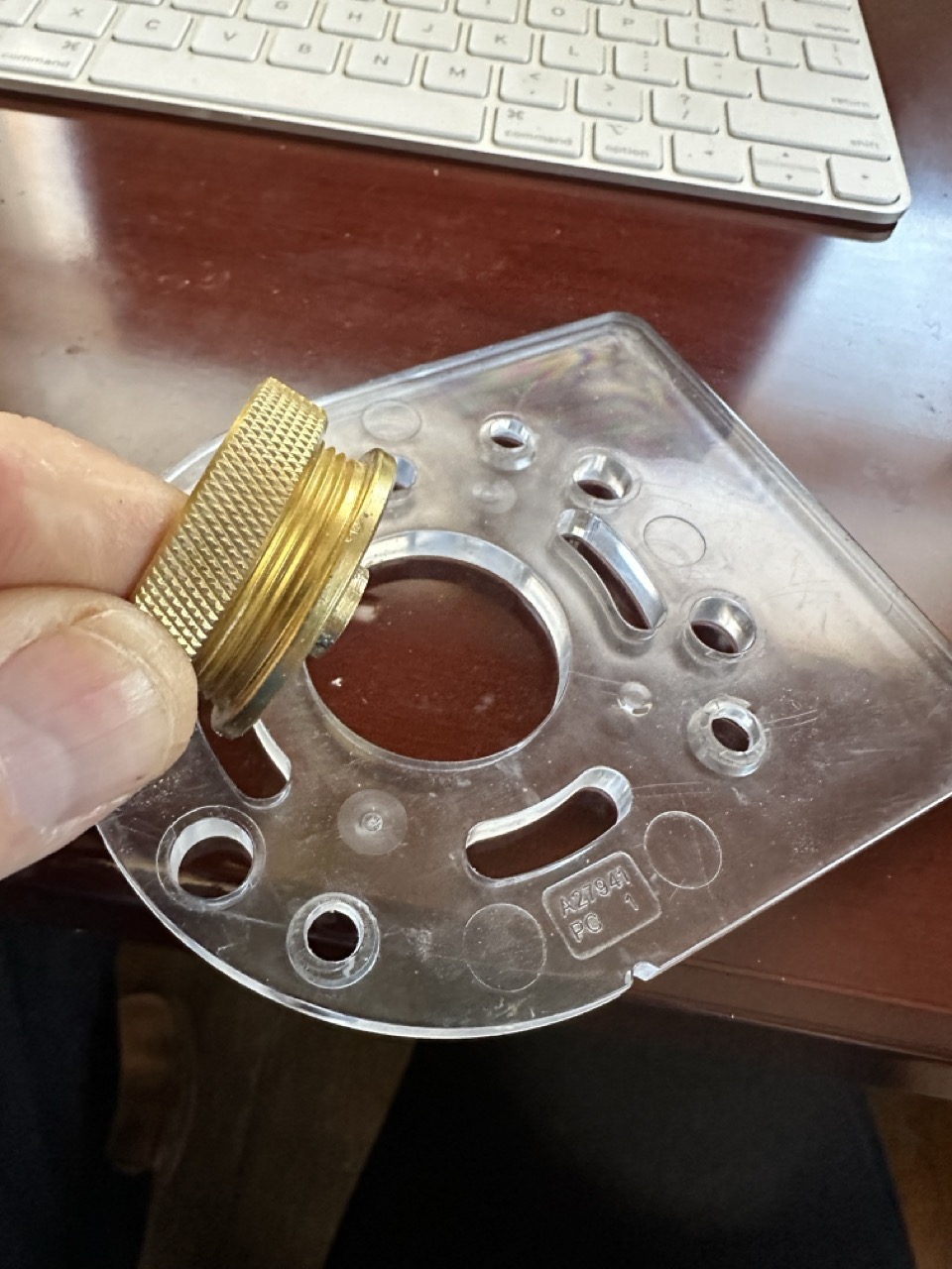
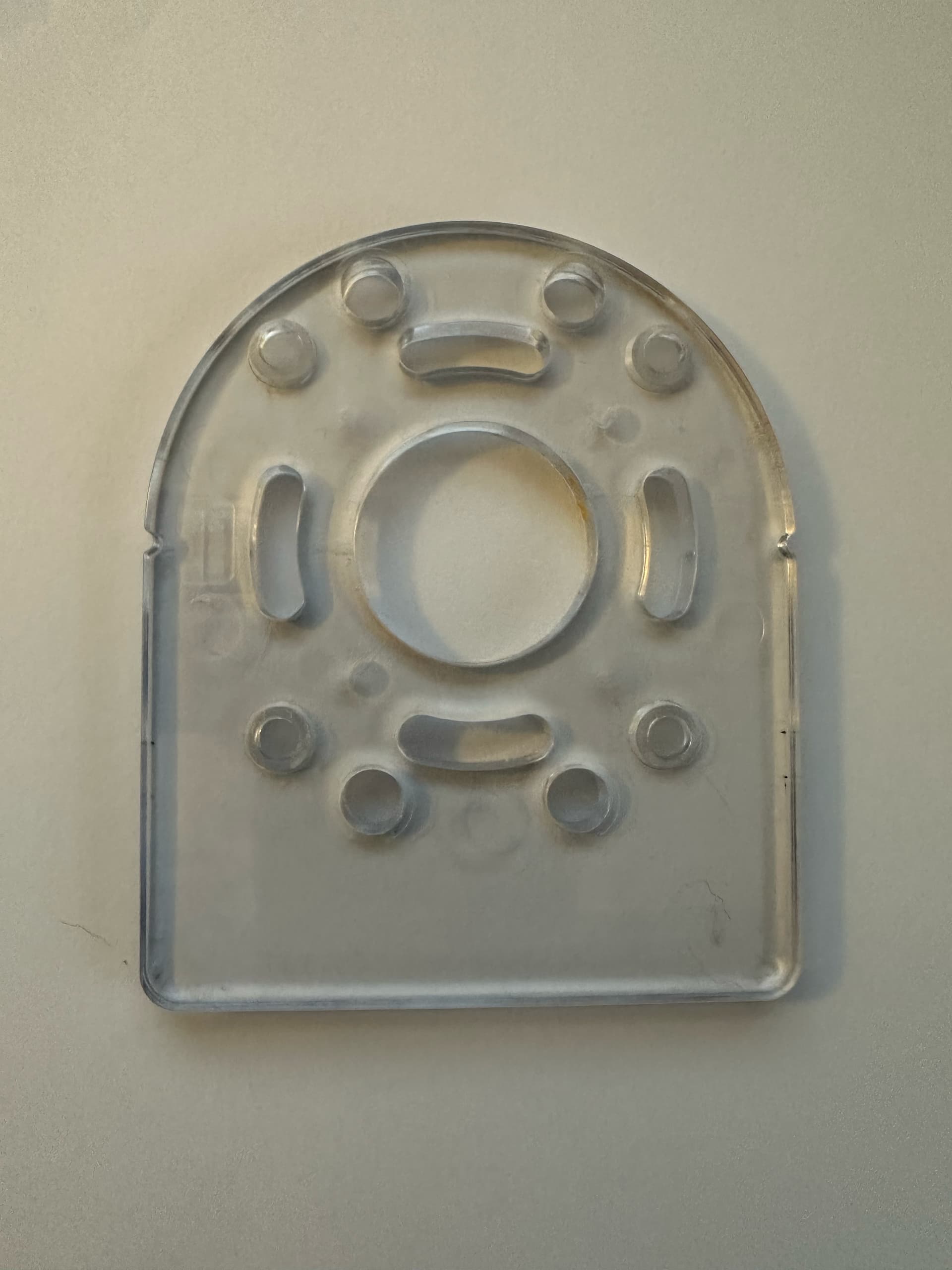
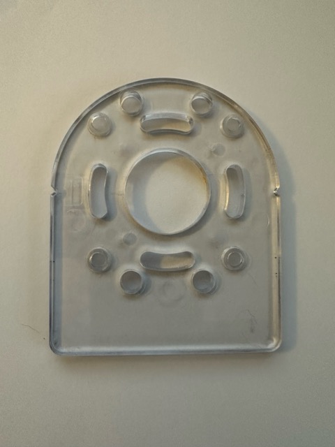
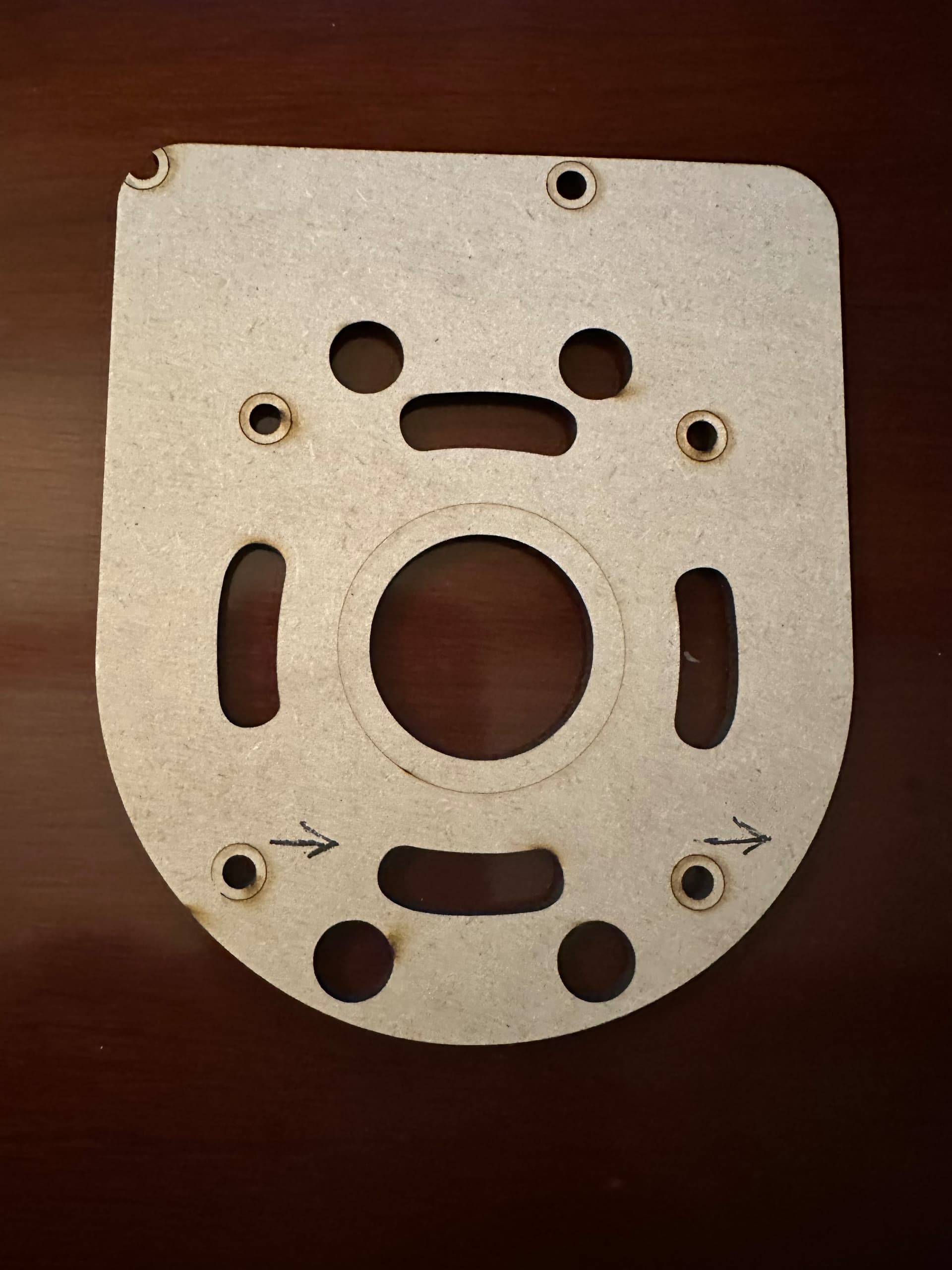
I am trying to design an Dewalt DCW600 router plate to fit a guide bushing for a dovetail jig. I emptying to flatbed scan my plate, but can’t get a good scan. Do you guys know any tricks? Do you auto cad people even have access to dewalt router plate schematics to load into LB?
Anyway, the threads on the guide bushing are 29.94 mm. I am going to say 30 mm.
If I can get a real life resolution scan of this plate, can I drop a 30 mm circle inside the original cut out hole of plate and will it center?
I am just trying ideas. I think there are plates out there to buy, but I haven’t found one for this router and a Rockler guide bushing yet. It also might be fun to make from 1/2 inch acrylic.
What’s preventing this? This is likely to get you the highest quality capture generally available.
If you’re having an issue with the clear acrylic perhaps cover it with dark masking tape or something similar and carefully trim away the tape where the holes are. The cleaner you can do this and get a clean scan the less processing you’ll need to do during the tracing process.
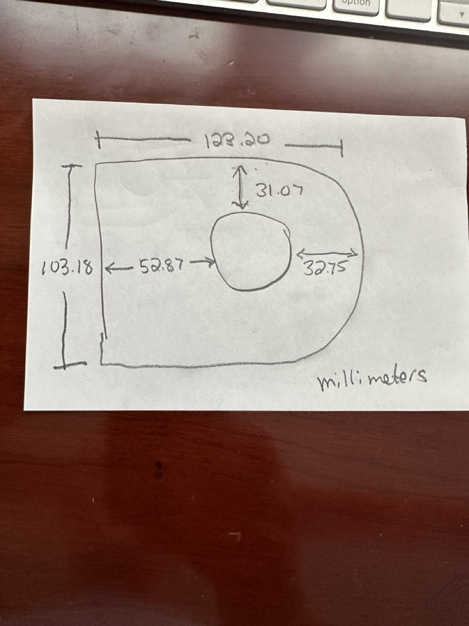
I’d also suggest taking very careful measurements that you can use to correct or validate traced scan. Do you have calipers or other measurement devices that can help you do this accurately? Hole size you could determine with drill bits or gauge pins if you have them.
I have caliper and haven’t gone that far yetI have a trace and measurements with a digital caliper. There is an architect at my maker space and said to measure it and split it into rectangles. he said something about the center line of the shoe should line up with the edges of the two rectangles. One made of the radius and one made out of the square side. See the measurements I am uploading in the .jpeg. I almost worried about the red layer holes. They are the center hole and the screw holes for mounting. But, the distance from the back to the center 52.87mm does’t match the drawing in FB. I think I expanded the black original trace lines to my original measurements.
Here is your file back. My interpretation is on layer 27.
Is it right? I don’t know. Best guess with what I had to work with. Dewalt router DCW600 Plate.lbrn2 (128.3 KB)
Jegg, I think I went into your file and added my 30mm cut. Fuscha line. If I don’t need to add a kerf hopefully my guide bushing will screw in and remain flush. I will let you guys know what happens when I get back to the laser. Cheers. Dewalt router DCW600 Plate 30mm circle.lbrn2 (28.6 KB)
Just a couple points to keep in mind. This manufacturer designs in metric. Most do these days. So when I reverse engineer something most of the dimensions are likely rounded to the nearest mm. So you guess based on an inaccurate part and caliper. Screw centerlines are the most important.
second point is that lasers are incredibly versatile however they can’t cut counterbores. Which you will need for the four screws and that 30mm insert. A router and jig would cut the 30 counterbore depending on how much time you want to put into it.
Copy that. I have a wood shop, a large drill press and a set of Forstner bits. I am going to cut the router bores with the Forstner if I can. I really wish I had access to my father’s micrometer. Maybe have the laser cut a pin hole as a guide. I can cut the countersink and then the though hole. These plates are on ETSY, but not for my particular dovetail jig and the guide bushing that is specific for that jig. That is why I am having to build one. If it works, great. If not, I have learned more about reverse engineering and more in LB. Thanks for the input.
PS, this may need “some bumping around” a few times to get things to line up properly.
I like your approach, use the accuracy of the laser to layout the part features then use a drilling tool to complete the feature. This reduces the tool walking you get from the wood grain. Lasers blast thru wood grain, but steel buts tend to struggle.
Lasers are about 2.1D and this is a 2.5D part. So your going to need to help it out with some post processing.
So far I have this. I am coaxing the X and Y axis of the two holes with arrows into final position. I have made about 6 test burns in MDF and the bushing fits right into the center hole. The bushing appears to fit, bit center via an eyeball check. I will know I have it when I test it out on the jig, and if the dovetails come out perfect, I will know I have this thing correct. the bottom screw holes are off my 10ths of a mm and will take some trial and error.
Here is an ask. Can I make a tool line and center it on my upper screw hole, and then center the lower screw hole to the tool line. Or just make a regular line. I don’t know how complicated that will be, but what is the best tool to use to pull two objects to center? I have problems with the centering and alignment tools. Just my lack of knowledge and experience.
I haven’t tried to do technical layouts in LB, but I don’t think you can snap an object to an endpoint and have it be persistent like a CAD constraint. I believe you can draw a line and edit the length to the desired value, then snap a circle to each end point. Could do the same with a rectangle and snap to corners or (I believe) midpoints. You can set the “construction” objects to either a tool layer or normal layer that’s set to not output. A line crossing from corner to corner of a rectangle could (again, I think) be used to find/snap to center. I’m not aware of a way to snap a circle tangent to a pair of intersecting lines, but one may exists. The alignment tools, in my experience, work pretty good if you select the objects in the right order. Also, don’t forget you can lock objects using the shape properties window.
I will give that a shot. Like I mentioned I am now down to just “nudging” in the x and y axis, but for some reason, I overshoot or keep undershooting. Thanks.
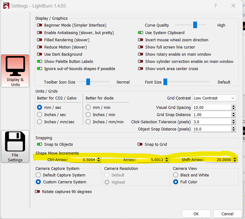
Nudging using the arrow keys or direct input of the coordinates (up in top toolbar, left of the size display, “XPos” & “YPos”)? You can adjust in effectively imperceptible increments using that. (.001mm, .00004")
Can you set that in preferences? I am on an M2 Mac book at home, but at the maker space they have win 11 running on a PC hooked up to the thunder. I am all thumbs when it comes to windows. When I try to nudge with my arrow kets here at home, the object jumps quite a bit. I didn’t know you could set the distance. Again I am still learning the smaller intricacies of this program.
I’m not sure if you can set the arrow move increments or not. I want to say yes, but I could be wrong. I think arrow alone is 1mm. Arrow+shift is 10mm and arrow+Ctrl is .1mm. Or something similar to that.
I haven’t used an Apple computer since the 80s, so I can’t help there. I know there are some minor differences in keyboard keys. I think “control” is one of them. I wanna say Apple uses a symbol that looks kinda like a pound sign with looped corners?
The position display should be visible by default. I don’t remember enabling it, but I may have. I’m that guy that generally likes to have all the information visible at once, so I tend to turn on advanced mode and/or make everything visible during initial setup.
The conversation may have drifted since you posted those photos. If the question is how best to lay this out in Lightburn here’s my recommendation:
Draw any square or rectangle
Resize to square of 61mm
Draw a circle or oval
Resize the circle to 30 or whatever
Align both shapes (together) vertically and horizontal A handy tool.
Draw one (then copy) or four 1mm circles and snap or attach them to the corners of the square.
Delete the square.
The center of the circle is now the axis of the router bit. The 1mm holes serves as a pilot for your forstner or drill bits.