I think it measures with the HG-C1100 Panasonic sensor right up to where the laser fires (it’s slightly tilted), perhaps a bit off to avoid measuring inside the cut when it’s cutting.
The issue with measuring at just one point is that when it encounters sudden jumps, like when it comes across another wooden board, it will inevitably collide with it because the system has a certain reaction time.
If I were to implement an all-terrain, production-ready system, I would use a matrix of measurement points to be prepared for abrupt jumps in any direction.
However, in practice, we don’t engrave under such conditions but only on slightly warped wooden boards or on acrylic that may not be perfectly level due to honeycomb bed imperfections. In this case, and this might give you an idea, I would implement a PID algorithm in the controller’s firmware.
I would love to see a system that measures the height at every point of what you’re engraving by projecting a grid of lasers and calculating its shape with the help of one or two cameras. This would allow to keep using a lightweight head while being able to adjust the height with an all-terrain paradigm and without mounting the sensor on it. However, I believe that would likely be beyond the budget of most people
If someone decides to undertake such a venture, I’d be willing to get involved, with proper market research, of course.
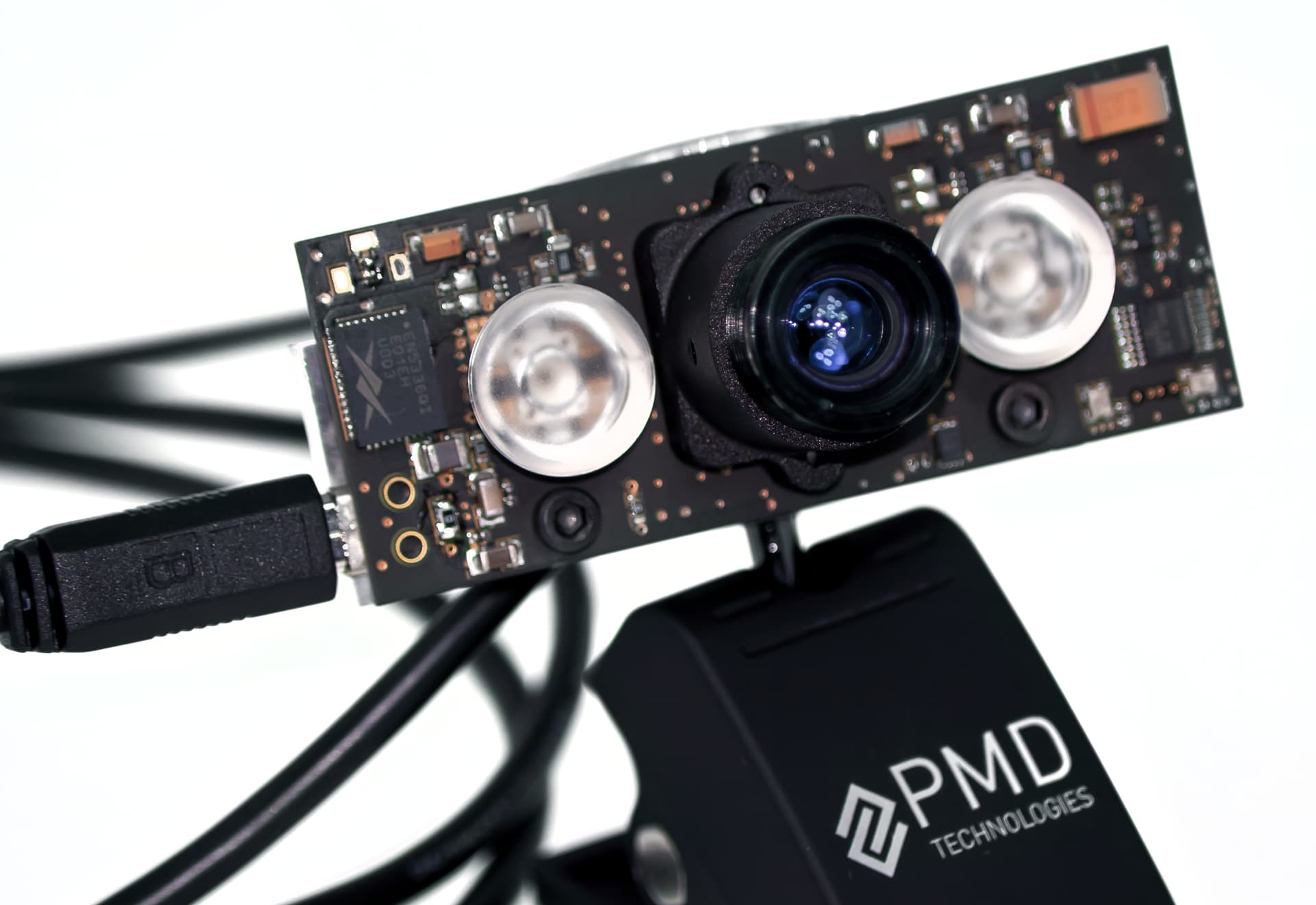
Or a lighter and more accurate system could be a TOF sensor, similar to the one incorporated into the Samsung S21 Ultra for assisting with autofocus.
3D TOF cameras work in a way similar to a submarine’s sonar or radar. They are used to precisely measure the distance to an object by projecting an infrared light beam towards it. When the light hits the object’s surface, a portion of it reflects back in the opposite direction to its initial propagation and returns to the camera. All the camera has to do now is calculate the time elapsed from when it emitted the light pulse until it received it after it reflected off the object. The speed at which the infrared light beam propagates is perfectly known because it’s the same as the speed at which visible light travels in the same medium.
lol, I am using an ESP32 as well. But seeing the discussion that just happened, I’m glad I had come to the same conclusion before! I am using 4 points of measurement and interpolate based on direction. It’s still not perfect, but it does avoid the problem of obstacles. As for holes, I use a per-job zeroing to avoid going lower than the 0 point, but on a large convex surface with large intermittent openings, it would still be a problem.
Anyways, re-doing the design at the moment because I was using an ESP32-S3 which has problems with some i2c devices. I’ve done a lot of troubleshooting and there are multiple i2c devices I just can’t get to work on the S3 that have no issues on the original ESP32.
I think you could memorize the bed’s height and not move the head vertically when you’re aiming at the bed (or below through a hole), but you know better the issues involved because you’ve dealt with it.
What I do find important, though, is that you use a PID algorithm to make sure you maintain a constant distance from your surface. Although having 4 measuring points will make it more complex, but also more accurate.
I’m sure you can adapt the code from some PID line follower car, but instead of using the differential of black/white, you’ll be using the differential of your focusing distance.
hum, I like the idea of memorizing the bed. The issue I could see is with honeycomb tables though, but it does otherwise solve the issue of misinterpreting holes as dips!
yes, the lowest part is what I am planning on using as the stop. I guess even with honeycomb, anything that is as far or further than the 0 is to be treated the same anyways.
Hello! To everyone who has been following this project, I am at the step of ordering the next iteration of the prototype. I don’t know if this goes against forum rules (I did ask an admin, but have not yet gotten a response). Unfortunately, I am a bit tight budget wise these days, and the next prototype will cost another 140 USD all in. I don’t think this product is ready for a kickstarter, so I was wondering if anyone would be interested in contributing. Id be willing to provide a working prototype PCB when we get to that point. It is a leap of faith as there is no guarantee this iteration will work. That being said, I’ve already designed multiple devices in the past (mostly for internal use) and am confident I can see this project through. So if anyone would like to sponsor the project, please reach out. Otherwise I will just have to be a bit more patient
We’d be happy to sponsor your next round of development, provided you continue to keep us abreast of your progress here on the forum DM incoming for details
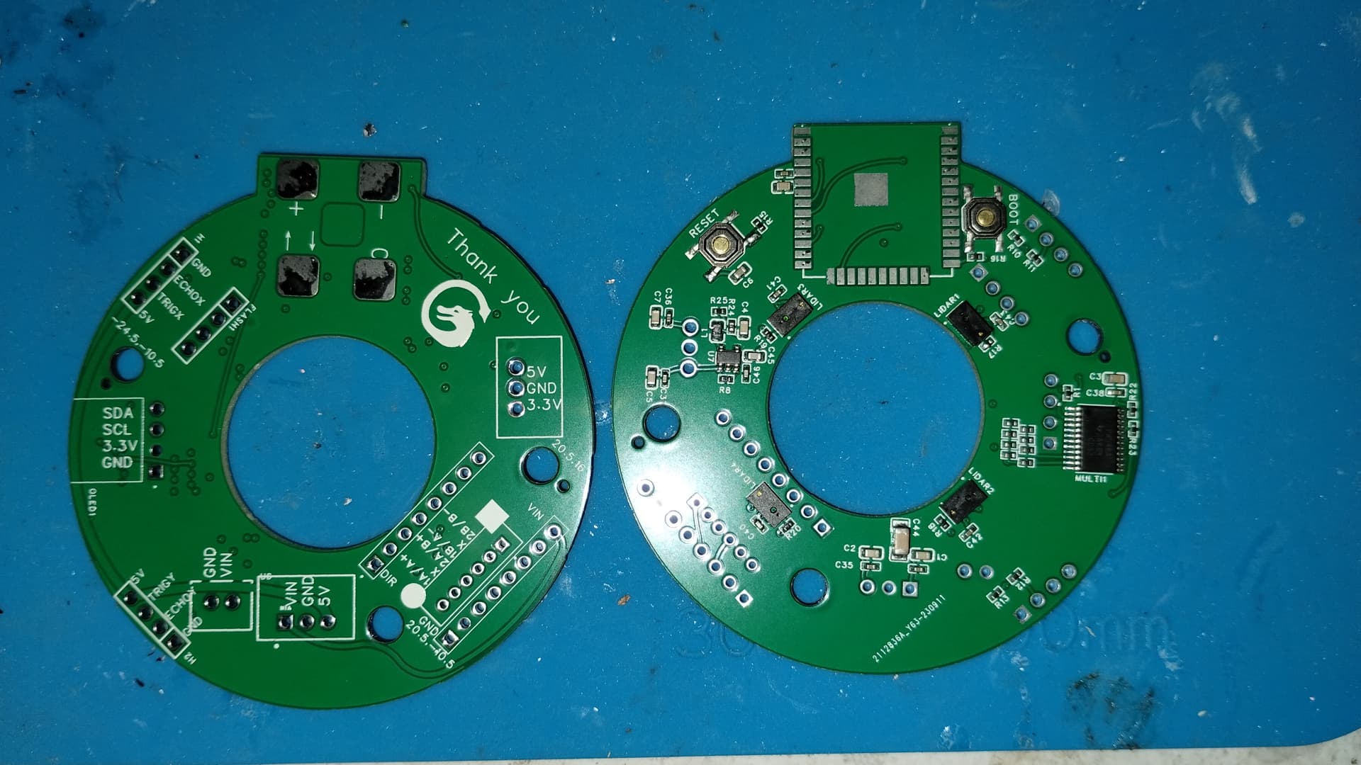
Alright, took an extra bit of time because I wanted to add a “thank you” + lightburn logo to my PCB silkscreen + weekend activities with the kids, but it’s done! Order placed… now I wait 10-15 days for delivery of the V3 prototype boards.
The new boards, pre final assembly! (they’re already dangling with extra wires and mods )
So the multiplexer is now confirmed to work properly. Ultra sonic x and y axis distance / speed meters are fine. LiDAR I now have semi working. I have to figure out if I can get my design to work with one modification (will test tomorrow), or if I have to go with the larger module (cheaper, confirmed working, but takes up more space and ads weight). So either way I’ll be happy honestly, but it would be nice to be able to keep the board compact and fully premanufactured by the pcb house instead of having to add these secondary modules and likely extra standoffs to avoid vibrations affecting readings. On the ultrasonic sensors, the fact that it’s an external module is unavoidable since it has to be perpendicular, but it’s also on the many cm scale, not 0.1mm scale, so the vibrations are trivial.
Anyways, once my measurement hardware is all good and ready, I’ll finally add the motor driver and motor and then start fine tuning the firmware and the compensation algorithm.
After that I’d like to get to work on a little web server interface so I can drop the OLED and buttons and the whole thing can be controlled via your phone (I would give it the LAN or access point setup options for those who don’t trust it on their network, but it wouldn’t use the internet either way, it’s just for setting custom speeds and acceleration).
Finally, low on the priority list, I want to add some status led for power ( since the board uses 12v, 5v, 3.3v, and 2.8v, all from the 12v supply), as well as for the Wi-Fi ststus (AP/LAN/error).
Is there anyone who would like to help on the mechanical aspect? For now I plan on keeping it dead simple with a pinion gear or worm screw and a straight teethed bar (don’t know what those are called), but I’d really like to move to a belt design because it would theoretically allow us to put the motor in a position with a better center of gravity, have less backlash, and be more system agnostic since you can just use different length belts to account for different lens tube designs.
ALL THE SENSORS WORK!!!
Thanks again to the @LightBurn team for allowing me to move this project forward by helping out with a prototyping round.
Of course, now that I finally have all 4 LiDAR working, my displayed measurement is no longer working (whereas with only 1 it was measuring fine), but that’s clearly software and costs time, not money to move forward. Super excited, it will be great to do this.
Funny enough, as I speak I am running a design that has massive fill areas that I am using to make 6 20cmx7cm 3/32 recessed areas in 1/8 ply (Canada eh?) and the heat from the job is causing the ply to bulge despite the metal frame I built to hold everything in place. This job would have been perfect for the Z axis compensator!
I’d have a few more ideas here. Maybe I can describe those later (not that much time at the moment). But one idea considering the weight at the head could be to not control the head height, but the bed height. The ESP could be used to control the bed height adjustment wirelessly, no need of a driver and motor at the head side then. But of course this means either disconnecting the bed height adjustment from the original controller or integrating into the control process, which won’t be easy.
I can explain more when I’m at home I designed a simple z-axis adjustment for diode lasers, but this adds quite some weight to the head. Automatic z-axis / focusing - Diode Laser Wiki