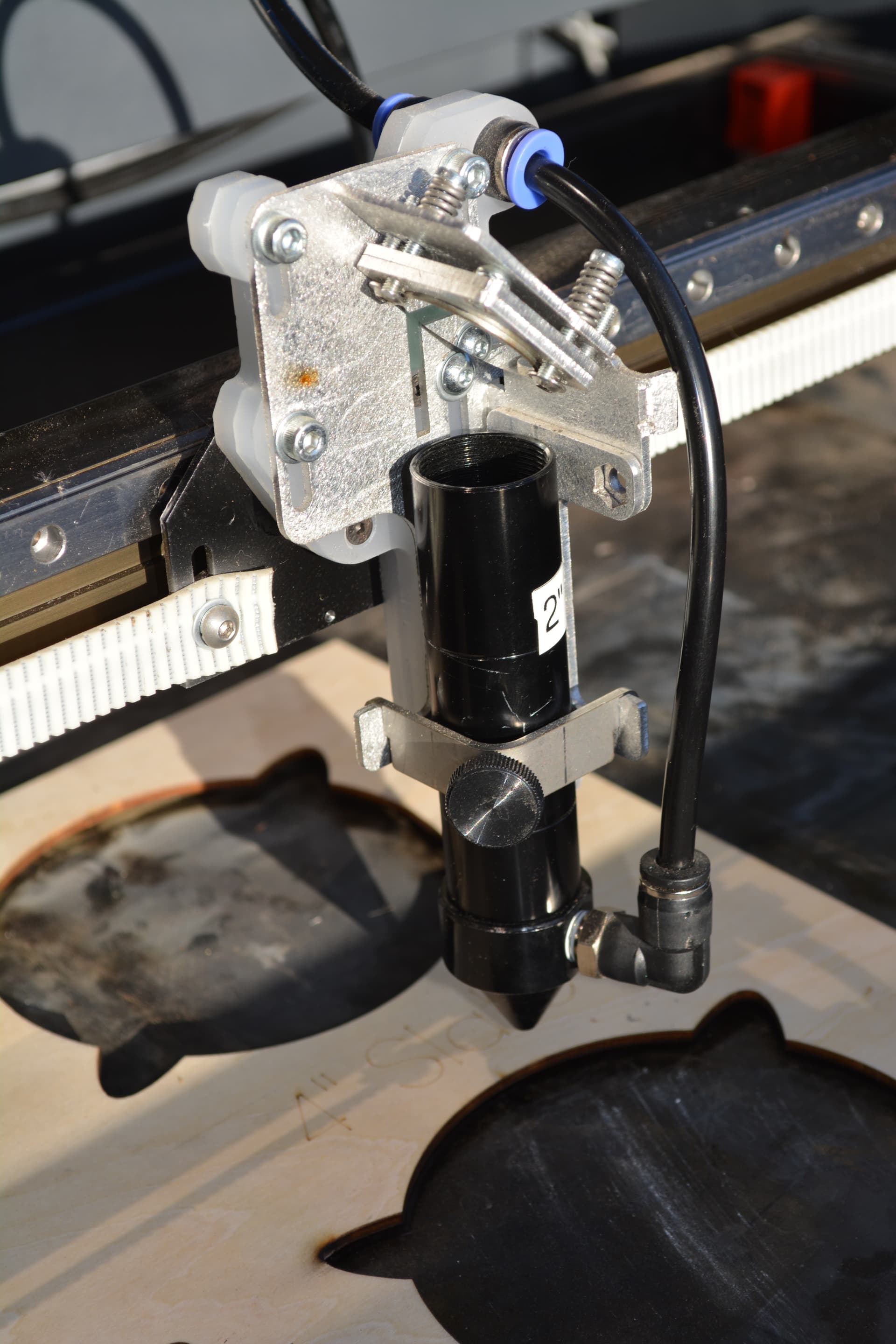
Hello, I work a lot with fairly large 3mm sheets (50cm x 30cm +) and warping is quite an issue for me, so I’ve decided to design a live servo z height compensator with 0.1mm resolution. The idea is to make it stand-alone and self contained so it can be attached to the lens mount. All it would need is a 2 wire 5v feed. I am wondering how much interest there would be for this and what value to see for it (as in how much is it worth to you in $ so I can know how much to spend designing this and how to design it… Just for me or for production).
It would likely require mechanical adaptors for different models which is a separate issue, but more straightforward to solve.
I’ve already figured out how to avoid crashing into cut holes, and interpolation matrix resolution depends on price point.
There are issues… first is the response or how fast will it have to respond to a change in height? How would you detect it…? if it’s a mechanical switch would it only be effective going in one direction? Is the detector is on the opposite side of the head?
You’d virtually have to drag it on the material for it to maintain in contact. The only right place for it to measure would block the beam.
I look at this a bit differently… seems many of us have engraved items we’d like to lase… image following a 3d engraving of a ship and following it… that would be response time and how your detector and it’s position would have to deal with… much less of a problem with flat 3mm stock, but for a precise focus, these become issues…
I have a smaller bed co2 and cut lots of 3mm, so I know the problems you must have with larger sheets. I use 2’ square pieces, I usually use magnets to hold them down… It would be nice to have something like this for natural products…
Put your thinking cap on… if you can pull it off, no telling…
There are small 3d distance detectors components… These are getting better…
They do have some of these for metal cutting lasers, these are hall effect and only work on Ferris metals.
Even some kind of ultrasonic detector for a micro might be applicable to at least make a proof of concept model.
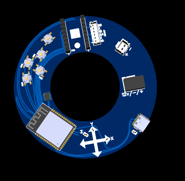
Almost done with the design of my first proof of concept. It’s based on 4 Lidar modules with a 0.1mm resolution and an accelerometer to know which Lidar to follow. combine that with 1/32 step NEMA motor ( so 0.05625 degree turn precision) and I think I can keep it hovering in a much more usable region than what I have now.
It mounts around the lens and drives a servo motor that keeps adjusting the height on the fly. The sensors are about 65mm / 3 inches apart and the height adjustments will be done live at full speed. The accelerometer senses G force / acceleration, and with acceleration and time I can get distance travelled. So at all times I can know how far I am from the measured points. Either that or I’ll use interpolated heights generated by using weighted height readings from 4 lidar sensors according to the corresponding G force. So if you’re 2G Y and 1G X for example, the +Y lidar is weighted double as we assume the slopes are more or less uniform / graded across a few inches (as they would be with warped wood). So in that example, a 0.1mm rise on +Y and a 0.5mm rise on +X would mean an interpolated rise of 0.35mm. I hope both approaches kinda work, because they could be combined. The idea is that the focus of the lens would always hover in a ±0.1 or 0.2mm window instead of what I have now which is either being 10x futher than I’m supposed to be, or dragging along the wood when I get to the high spots…
The biggest part of the weight will be the NEMA 8 motor, but even that is just shy of 2 cubic inches (about 1x1x2). It weights 80g + the other parts, I think the whole thing should weigh under 150g or 1/3lb. The idea is to hug it near the center though to avoid backlash from being introduced.
Power consumption is once again mostly the motor, it should not exceed 5W draw altogether, so it could even be run of a AAA battery with a DC-DC booster if you really didn’t want to run the 12v wire input.
I’m going to be working with Yousef form Spark Laser to design the mechanical part of it (since he designed my machine) and then we’ll see about making a K40 version and releasing it into the wild!
The real dream would be having some sort of piezo autofocus lens, but that would be pretty nuts and the goal here is to make this accessible for mods, and hopefully creative uses of the mechanism.
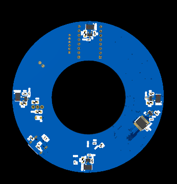
LOL! when you put it that way… Truth is I have no idea how much the whole thing is going to weigh in the end, but you bring up a good point… Alright fine, I’ll do some math lol. The PCB would only weigh about 15-20g, so really the balance of the weight is the wiring and the actuation mechanism (the gears and whatnot). The “fixed” weight would be the circuit board and the motor which would come in around 95g.
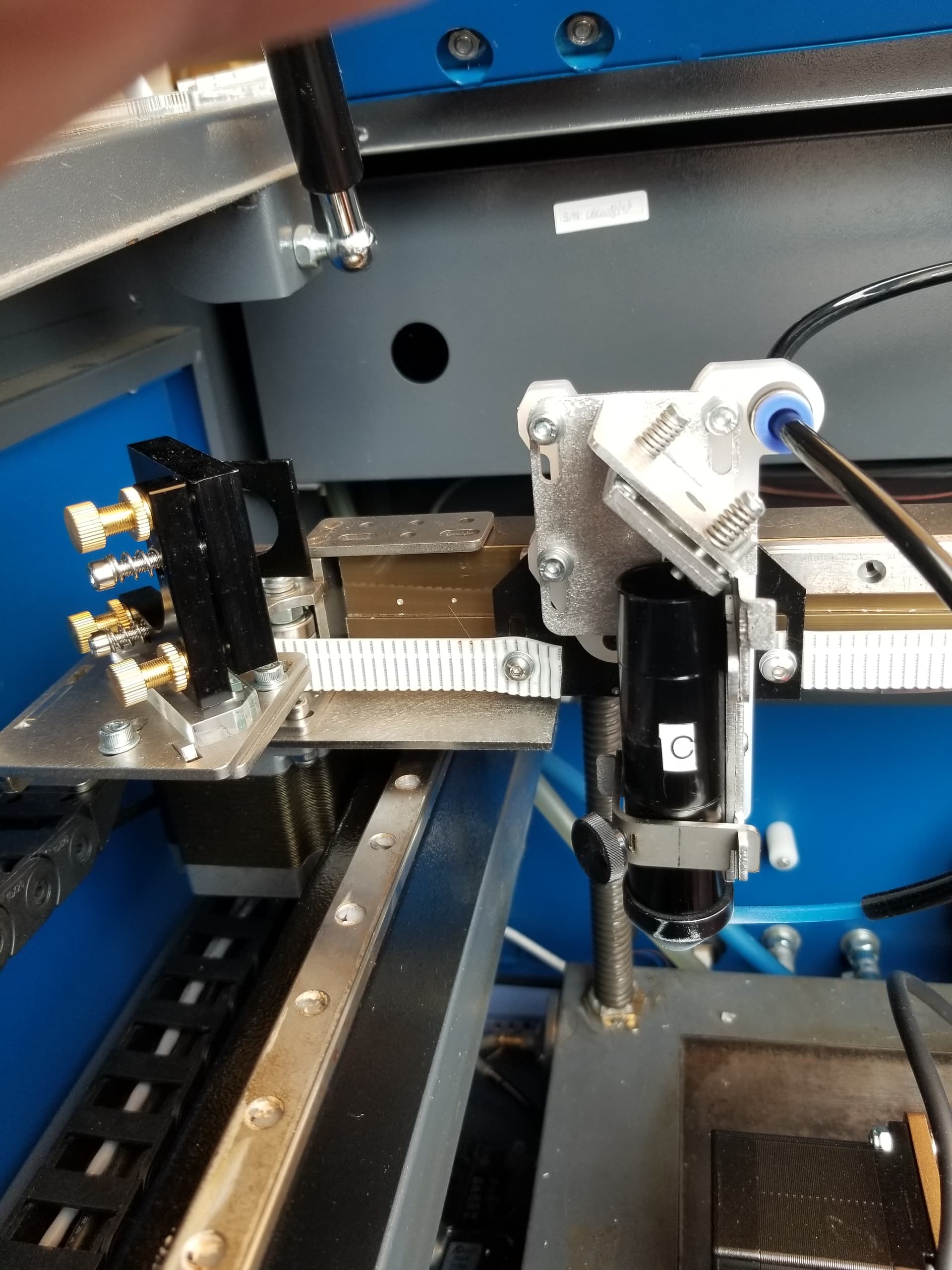
Lol! Turns out I’ve been posting updates in DMs with Colin for those following, I had my first prototypes arrive, did lots of tweaking, and the second version just arrived at half the size. Next testing should happen this coming weekend.
Alright, project update. I have had the chance to take a look at my new revision of hardware. There are some minor adjustments, but I can’t get the LiDAR chip to communicate for some reason. I’ve been able to use an oscilloscope to see that the signal is getting through from the ESP32, through the multiplexer, and to the chip… now why it won’t respond is baffling me. Still… I’ll keep at it.
From the video they clearly didn’t. Where they move it around at a pretty low speed, it hits objects on the table and knocks them around …
That would indicate that it’s position is taken from a different location than the tip of the nozzle.
The measurement point should be where the laser strikes, but that’s pretty impossible. I suspect it’s at a specific point somewhere around the lens. It appears to knock materials off no matter what direction it going…
Too bad I don’t read/understand Russian, or for that matter Chinese
It would be nice to know more details.
I strive for a lightweight system, this just adds a ton of mass to the head… Might not matter on that beast…